Take Off / Go Around (TOGA) - Explained

Performing Go-Around can be a confusing procedure, made more so by the effects of inclement weather. 

TO/GA is an acronym for Take Off / Go Around.  TO/GA is used whenever an approach becomes unstable or environmental conditions alter that do not allow an approach and landing within the constraints that the aircraft is certified.  If you watch the short video (embedded from U-Tube) you will note that the crew utilized TO/GA when a rain squall reduced visibility to almost zero as the aircraft was about to cross the runway threshold.


VIDEO: Boeing Business Jet (BBJ)  - Final Approach engaged TO/GA due to inclement weather (courtesy & copyright "DougLesso" U-Tube).

So why is TO/GA confusing?  It’s not the actual use of TO/GA that is confusing, but more the level of automation you have in use at the time of engaging TO/GA.  By automation, I am referring to  the command mode selected for the approach: VNAV, LNAV, V/S, ILS and whether the autopilot is enaged or not (CMD A/B).  In this post three three distinct scenarios will be discussed; however, engine out (single engine) procedures will not be examined.

Scenario One

Autopilot Flight Director System (AFDS) configured for autoland:  CMD A & B engaged with localizer and glideslope captured and 'FLARE armed' and annunciated on the Flight Mode annunciator (FMA).  Auto throttle engaged.

  • Pushing the TOGA buttons will engage the Take Off / Go Around mode & Flight Director guidance will 'come alive';

  • The auto throttle will automatically move forward to produce reduced go around (RGA) thrust;

  • The Thrust Mode Display (TMD) will annunciate TO/GA and the required thrust will be displayed;

  • The autopilot will remain engaged and will pitch upwards to follow the Flight Director (FD) guidance

  • Landing gear will need to be raised and flaps retracted on schedule; and,

  • A 'bug up' will be observed on the speed tape of the Primary Flight Director (PFD) which indicates flap retraction speeds.

Scenario Two

Autopilot Flight Director System (AFDS) configured for manual landing (autopilot on):  CMD A or B engaged.  Auto throttle engaged.

  • Pushing TO/GA buttons will engage the Take Off / Go Around mode & Flight Director Guidance will 'come alive';

  • The auto throttle will automatically move forward to produce reduced go-around thrust.  However, the autopilot will disconnect;

  • The Thrust Mode Display (TMD) will annunciate TO/GA and the required thrust will be displayed;

  • The crew will need to take control and manually fly to follow the Flight Director guidance (around 15 Degrees nose up);

  •  Landing gear will need to be raised and flaps retracted on schedule; and,

  •  A 'bug up' will be observed on the speed tape of the Primary Flight Director (PFD) which indicates flap retraction speeds.

Scenario Three

Autopilot Flight Director System (AFDS) configured for manual landing (autopilot off):  CMD A or B not engaged.  Auto throttle engaged/not engaged.

  • Pushing TO/GA buttons will engage the Take Off / Go Around mode and Flight Director guidance will 'come alive';

  • The crew will need to take control and manually fly to follow the Flight Director guidance (around 15 Degrees nose up);

  • The auto throttle will not command reduced go around thrust.  The crew must manually move the throttle levers to roughly 85% N1;

  • Landing gear will need to be raised and flaps retracted on schedule; and,

  • A 'bug up' will be observed on the speed tape of the Primary Flight Director (PFD) which indicates flap retraction speeds.

The black TOGA buttons are prominent on each of the thrust levers. OEM 737-800 throttle quadrant

How is TO/GA Engaged

The Boeing 737 has two buttons on the throttle quadrant for engaging TO/GA.  These buttons are located on each thrust handle below the knob of the thrust levers.  The TO/GA buttons are not the buttons located at the end of each throttle knob; these buttons are the auto throttles (A/T) disconnect buttons.

Pushing one or two of the TO/GA buttons will engage the go-around mode and command Flight Director guidance for attitude pitch.

Depending on the level of automation set, but assuming minimal automation, the pilot-flying may need to push the throttle levers forward to roughly 85% N1 (Reduced Go Around Thrust).  Boeing pilots often refer to this technique as the 'Boeing arm' as an outstretched arm grasping the throttle levers moves the levers to 'around' 85% N1.

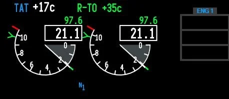
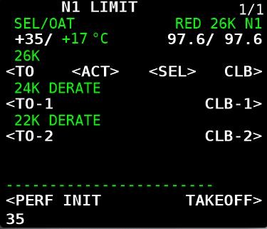
fma displays for toga

If the crew pushes the TO/GA button once, reduced go-around power is annunciated on the Thrust Mode Display (above the N1 indications on the EICAS screen) and also in the Flight Mode Annunciator (FMA).  Reduced go-around thrust is roughly 10% below the green coloured reference curser on the N1 indicator.  This thrust setting will generate a rate of climb between 1000 and 2000 fpm.

Flight Mode Annunciator (FMA) on Primary Flight Display (PFD) indicated TOGA and TOGA will be displayed on Thrust Mode Display (TMD).  Replace CRZ (1) with TO/GA

If the TO/GA buttons are pressed again (two button pushes), go-around thrust will be set to maximum thrust (at the reference curser). Engaging the TO/GA button twice is normally only used if terrain separation is doubtful.

A Typical Go Around (CAT 1 Conditions)

The pilot flying focuses on the instruments as the aircraft descends to about 200 feet AGL.  The pilot not flying splits his attention between his responsibilities to both monitor the progress of the approach, and identify visual cues like the approach lighting system.   If the approach lights of the runway come into view by 200 feet, the monitoring pilot will announce 'continue' and the flying pilot will stay on instruments and descend to 100 feet above the runway.

If the non-flying pilot does not identify the runway lights or runway threshold by 200 feet AGL, then he will command 'Go Around Flaps 15'.  The pilot flying will then initiate the Go Around procedure.

The pilot flying will engage the TOGA command by depressing the TO/GA buttons once, resulting in the Flight Director commanding the necessary pitch attitude to follow (failing this the pitch is roughly 15 Degrees nose up).  The auto throttle (depending on level of automation selected) will be commanded to increase thrust to the engines to attain and manage a 1,000 foot per minute climb; a second press of the TOGA buttons will initiate full thrust.  

The pilot not-flying will, when positive rate is assured, raise the landing gear announcing 'gear up all green' and begin to retract the flaps following the 'bug' up schedule as indicated on the Primary Flight Display (PFD).  Once the Go Around is complete, the Go Around Checklist will be completed.   

Important Points to Remember when using TOGA

  • If the Flight Directors (FD) are turned off; activating TO/GA will cause them to 'come alive' and provide go around guidance.  

  • Engaging TOGA provides guidance for the flight modes and/or N1 setting commanded by the auto throttle, It will not take control of the aircraft.  If the autopilot and auto throttle is engaged then they will follow that guidance; however, if the autopilot is not engaged the crew will need to fly the aircraft.

  • TOGA will not engage the auto throttle unless the autopilot is engaged.  The only way to engage auto throttle is with your hand (flip the switch on the MCP).  See sidenote below.

  • TOGA will engage only if the aircraft is below 2000 RA (radio altitude).

  • TOGA will engage only if flaps are extended.

  • Remember to dial the missed approach altitude into the Mode Control Panel (MCP) after reaching the Final Approach Fix (FAF). The FAF is designated on the approach plate by the Maltese cross.  This ensures that, should TOGA be required, the missed approach altitude will be set.

Side-note:  It is possible to engage the auto throttle using the TO/GA buttons if the auto throttle is in ARMED mode and the speed deselected on the MCP.  Note this method of auto throttle use is not recommended by Boeing.

Flight Crew Psychology

Flight crews are as human as the passengers they are carrying, but it’s difficult to accept that a Go Around is not a failure, but a procedure established to ensure added in-flight safety.  Several years ago airline management touted that a go-around required a detailed explanation to management; after all, a go-around consumes extra fuel and causes an obvious delay as the aircraft circles for a second landing attempt. This philosophy resulted in several fateful air crashes as flight crews were under time and management pressure to not attempt a go-around but continue with a landing.

Management today see the wisdom in the go-around and many airlines have a no fault go-around policy.  This policy is designed to remove any pressure to land in unsafe conditions - regardless of the reason: visibility, runway condition, crosswind limits, etc.  If one of the pilots elects to go-around, that decision will never be questioned by management.  So while TO/GA isn't the desired landing outcome, a go-around is not considered a failure in airmanship.

Minimal Discussion

This post has briefly touched on the use of TO/GA in an approach and landing scenario; nonetheless, to ensure a more thorough understanding, I urge you to read the Flight Crew Operations Manual (FCOM) available for download in the Training and Documents section of this website. 

Acronyms Used

  • AFDS - Autopilot Flight Director System

  • A/T - Auto Throttle Category 1 - Decision height of 200 feet AGL and a visibility of 1/2 SM

  • CMD - Command A or B (autopilot)

  • FAF – Final Approach Fix

  • FD - Flight Directors

  • FMA - Flight Mode Annunciator

  • FPM - Feet Per Minute

  • MCP - Mode Control Panel

  • N1 - Commanded Thrust % (rotational speed of low pressure spool)

  • RA - Radio Altimeter

  • RGA – Reduced Go-Around Thrust

  • TMD - Thrust Mode Display (on EICAS display)

  • TO/GA - Take Off / Go Around. Written either as TO/GA or TOGA

Avoiding Confusion: Acceleration Height, Thrust Reduction Height, Derates, Noise Abatement and the Boeing Quiet Climb System

Thompson B738NG transitioning to Thrust Reduction Height, Immediately following this will be acceleration height when the aircraft’s nose is lowered, flaps are retracted and climb thrust commences, acceleration will be reached, Manchester, UK (Craig Sunter from Manchester, UK, Boeing 737-800 (Thomson Airways) (5895152176), CC BY 2.0)

The takeoff phase of a flight is one of the busiest and most critical periods, and during this time, several distinct functions occur in rapid succession. While each function serves a unique purpose, they are intricately linked by the changing altitude of the aircraft.

Because they unfold so quickly, these functions often cause confusion for those unfamiliar with the process.

In this article, we will explore the following:

  • Acceleration Height;

  • Thrust Reduction Height;

  • Derated Takeoff Thrust (fixed derate);

  • Assumed Temperature Method (ATM);

  • Derated Climb Thrust (CLB-1 & CLB-2); and,

  • The Quiet Climb System (often called cutback).

Acceleration Height (AH)

Acceleration height is the altitude AGL that the aircraft transitions from the takeoff speed (V2 +15/20) to climb speed.  This altitude is typically between 1000 and 1500 feet, but may be as low as 800 feet; however, can differ due to noise abatement, airline policy, or airport specifics such as obstacles, etc.

The three main reasons for acceleration height are:

  1. It provides a safe height (AGL) at which the aircraft’s airspeed can be increased (transition to climb speed) and the flaps retracted;

  2. It enables a safety envelope below this altitude should there be an engine failure; engines are set to maximum thrust, and the aircraft’s attitude is set to maintain V2 safety speed (V2+15/20); and,

  3. It provides a noise buffer concerning noise abatement. Below acceleration height the engines will be targeting V2 safety speed (V2 +15/20) and will be generating less engine noise.

Acceleration height can be changed in the CDU (Init/Ref Index/Takeoff Ref Page (LSK-4—L) ACCEL HT ---- AGL).

Practical Application

Takeoff Ref page showing acceleration height OF 1500 FEET agL and thrust reduction height (thr reduction) OF 800 FEET AGL. BOTH CAN BE CHANGED AS REQUIRED

Once acceleration height has been reached, the pilot flying will reduce the aircraft’s attitude by pushing the yoke forward; thereby, increasing the aircraft’s airspeed.  As the airspeed increases to climb speed, the flaps can be retracted as per the flaps retraction schedule. It is important not to retract the flaps until the aircraft is accelerating at the airspeed indicated by the flaps retraction schedule (flaps manoeuvring speed indicator) displayed on the speed tape in the Primary Flight Display).

Assuming an automated takeoff with VNAV and LNAV selected, and once acceleration height is reached, the autothrottle will be commanded by the autoflight system to increase the aircraft’s airspeed to climb speed. If manually flying the aircraft, the flight crew will need to increase the speed from V2 +15/20 to climb speed (by dialling a new speed into the MCP speed window).

Although crews use slightly varying techniques; I find the following holds true for a non-automation climb to 10,000 feet AGL:

  1. Set the MCP to V2;

  2. Fly the flight director cues to acceleration height (this will be at V2 +15/+20);

  3. At acceleration height, push yoke forward reducing the aircraft’s attitude (pitch);

  4. Dial into the MCP speed window the appropriate 'clean up' speed (reference the top white-coloured carrot on the speed tape of the PFD, typically 210-220 kias);

  5. As the forward airspeed increases, you will quickly pass through the schedule for initial flap retraction (as indicated by the green-coloured flaps manoeuvring speed indicator – retract flaps 5;

  6. Continue to retract the flaps as per the schedule; and,

  7. After the flaps are retracted, engage automation (if wanted) and increase airspeed to 250 kias or as indicated by Air Traffic Control.

Note:  If the acceleration height has been entered into the CDU, the flight director bars will command the decrease in pitch when the selected altitude has been reached - all you do is follow the flight director bars.

Thrust Reduction Height (TRH)

upper display unit (eicas). Thrust reduction can easily be observed as the N1 lowers slightly when the aircraft reaches the entered thrust reduction height (image copyright FCOM)

The main wear on engines, especially turbine engines, is heat. If you reduce heat, the engine will have greater longevity. This is why takeoff power is often time limited and the thrust reduced at and a height AGL. The difference between takeoff thrust and climb thrust may vary only be a few percent, but the lowering of EGT reduces heat and extends engine life significantly. 

The thrust reduction height is the height AGL where the transition from takeoff thrust to climb thrust takes place.  Acceleration height comes soon after.

The height used for thrust reduction, not taking into account noise abatement, can vary and be dependent on airline policy. Typically it falls between 800-1500 feet AGL. 

Possible reasons for selecting a higher height AGL at which thrust reduction occurs may be obstacle clearance (such as buildings, towers, etc) or environmental factors.

When the aircraft reaches the thrust reduction height, the resultant loss of N1 is displayed on the N1 RPM indication in the Upper Display Unit of the EICAS. The N1 is displayed in large white numerals (87.7) and is also indicated by the green-coloured N1 reference bug.

Confusion between Acceleration Height and Thrust Reduction Height

Newcomers are often confused between the two similarly-sounding terms, possibly because they both occur at the interface between takeoff and climb-out.  Simply written:

  • Thrust Reduction Height is the height AGL at which the takeoff thrust will be reduced by a few percent N1. This is done to increase engine life and lower maintenance. It is alos when the autothrottle will be commanded to decrease the takeoff thrust to climb thrust; and.

  • Acceleration Height is when the nose of the aircraft is lowered to increase airspeed. The flaps are then retracted as per the flaps retraction schedule.

    Both may occur simultaneously or at differing heights above ground level.  Both can be configured in the CDU.

To change the acceleration height: Init/Ref Index/Takeoff Ref Page 2/2 (LSL-4L)

To change the thrust reduction height: Init/Ref Index/Takeoff Ref Page 2/2 (LSL-5R)


Takeoff (derate 24K CLB-1). Note drop in N1 thrust as aircraft reaches 800 feet AGL (throttle reduction height). At acceleration height (1500 feet AGL) the flight director commands a pitch down. As airspeed increases flaps are retracted as per the schedule (ProSim737).


Reduced Thrust Derates (General Information)

Derates are not complicated; however, when they are discussed together, the subject matter can quickly become confusing; mainly because the names for the differing derates are similar. I have attempted to try and keep things as simple as possible.

Engine derates on a Boeing 737 refer to the intentional reduction in engine thrust during certain flight conditions to optimise engine performance, and increase the longevity of the engines. A derate involves limiting the maximum available thrust that an engine can produce under specific conditions.

Typically, the takeoff performance available from an aircraft is in excess of that required, even when accounting for an engine failure. As a result, airline management encourage flight crews to use a derate, when possible.

Purpose of Engine Derates:

  1. Safety and Engine Longevity: Derating can help prevent engine overstress and prolong the life of the engine, especially during takeoff and climb phases.

  2. Performance Optimisation: It can help maintain more efficient fuel burn, manage high temperatures, and reduce engine wear.

  3. Environmental Conditions: In cases of high ambient temperature or high altitude airports, derating helps reduce the engine's demand on performance.

Derates can be assessed on the N1 Limit Page in the CDU. The following derates, applied singly or in combination, are possible:

  • Derated Takeoff Thrust (fixed derate).

  • Assumed Temperature Method (ATM) ; and,

  • Derated Climb Thrust (CLB-1 & CLB-2).

When To Use a Derate

Possible reasons for using or not using a derate are:

  • Environmental considerations (runway condition, weather, wind, etc);

  • Ambient temperature;

  • Airport’s height above sea level;

  • The weight of the aircraft’s load including fuel;

  • Consideration to airline management;

  • The length of the runway; and,

  • Noise abatement.

Electronic Flight Bag (EFB) or Takeoff Performance Tables

A derate is not selected idly by the flight crew. Most airlines use an Electronic Flight Bag (EFB) or another approved source to calculate a suitable derate. If an EFB is unavailable, the aircraft performance data tables in the Flight Crew Operating Manual (FCOM) must be consulted, and the calculations done manually.

Using a derate is not always an option in all situations. For example, in high-performance scenarios, such as heavy takeoffs, high density altitudes, or congested airspace, full thrust may be required. Similarly, a derate may not be suitable if the weather is extremely hot, or if the aircraft is heavy and the runway is short. The final decision on whether to use a derate rests with the Captain of the aircraft.

Thrust Mode Annunciations and Displays

When a derate is used, the thrust mode annunciation (the annunciation is displayed in green-coloured capitals) will be displayed in the Upper Display Unit on the EICAS. The display will differ depending on the airline option.

Possible displays are as follows:

  • TO – takeoff (displayed if no derate is used) - option without derate.

  • TO 1 – derated takeoff 1 - option without double derate.

  • TO 2 – derated takeoff 2 - option without double derate.

  • D-TO – assumed temperature reduced thrust takeoff (ATM) - option with double derate.

  • D-TO 1 – derate one and assumed temperature reduced thrust takeoff (ATM) - option with double derate.

  • D-TO 2 – derate two and assumed temperature reduced thrust takeoff (ATM) - option with double derate.

  • CLB-1 – climb derate.

  • CLB-2 – climb derate.

We will now examine the derates available in the Boeing 737 aircraft.

1 - Derated Takeoff Thrust (Fixed Derate)

A fixed derate is a certified takeoff rating lower than a full rated takeoff thrust. In order to use a fixed derate, takeoff performance data for a specified fixed derate is required (Boeing FCTM 2023). This information is available either from the EFB or from the aircraft performance data tables in the FCOM.

The N1 Limit page in the CDU displays three fixed-rate engine derates: 26000, 24000 and 22000 (26K, 24K and 22K). Selection of a derate will command the software to limit the maximum thrust of the engines to whatever has been selected; nothing is altered on the actual engine. Selecting a derated engine thrust can only occur when the aircraft is on the ground.

Once a fixed derate is selected, it will remain in force until the aircraft reaches acceleration height or a pitch mode is engaged, at which point the fixed derate will be removed.

The N1 for the selected derate is displayed on the NI Limit page, the TAKEOFF REF page (LSK-2L) and in the N1 RPM indication in the Upper Display Unit (%N1 RPM readout and N1 reference bug) on the EICAS.

Thrust Limitation (Fixed Derate)

When using a fixed derate, the takeoff thrust setting is considered a takeoff operating limit. This is because the minimum control speeds (Vmcg and Vmca) and stabiliser trim settings are based on the derated takeoff thrust.

The thrust levers should not be advanced beyond the N1 RPM indication unless takeoff conditions require additional thrust on both engines (e.g., during windshear). If the thrust levers are advanced beyond the N1 RPM indication—such as in the event of an engine failure during takeoff—any increase in thrust could lead to a loss of directional control.

Important Point:

  • A fixed derate can be used on a runway that is either wet, has standing water, or has slush, ice or snow ( provided the performance data supports use of such a derate).

2 - Assumed Temperature Method (ATM)

The assumed temperature method is not exactly a derate; however, it has been discussed because the use of ATM can reduce takeoff thrust.

This method calculates thrust based on a assumed higher than actual air temperature and requires the crew to input into the CDU a higher than actual outside temperature.  This will cause the on-board computer to believe that the temperature is warmer than what it actually is; thereby, reducing N1 thrust. This reduces the need for full thrust, achieving a quieter and more fuel-efficient takeoff.

Using ATM, the desired thrust can be be incrementally adjusted by changing the temperature to a higher or lower value. This can be an advantage to a flight crew as they can fine tune the thrust setting to exactly what is required, rather than using a fixed derate.

ATM is effective only above a certain standard temperature. The 737 Next Generation engines are flat-rated to a specific temperature. In the case of the CFM-56, this is ISA +15°C or 30°C on a standard day. This means the engine can provide full thrust up to that temperature. However, if the temperature exceeds this limit, the engine will produce less thrust. When ATM is used, the temperature must always be set higher than the engine’s flat-rated temperature. Otherwise, the engine will continue to provide full thrust.

Once ATM is selected, it will remain in force until the aircraft reaches acceleration height or a pitch mode is engaged, at which point ATM will be removed.

The desired thrust level is obtained through entry of a SEL TEMP value on the N1 Limit Page (LSK-1L) or from the Takeoff Ref Page 2/2 (LSK-4L).

To delete an assumed temperate the delete key in the CDU should be used.

Thrust Limitation (ATM)

An ATM is not the same as a true derate, even though the takeoff thrust is reduced. This is because when using ATM, the takeoff thrust setting is not considered a takeoff operating limit, since minimum control speeds (Vmcg and Vmca) are based on a full rated takeoff thrust.

At any time during takeoff using ATM, the thrust levers may be advanced to the full rated takeoff thrust (Boeing, 2023 FCTM; 3.17).

Important Points:

  • ATM may be used for takeoff on a wet runway, provided the takeoff performance data (for a wet runway) is used. However, ATM is not permitted for takeoff on a runway contaminated with standing water, slush, snow, or ice.

  • During an ATM takeoff, the yoke may require additional back pressure during rotation and climb.

  • If another derate is selected in combination with ATM, the calculation for takeoff thrust is accumulative. Selecting more than one derate can affect the power that is available for takeoff and significantly increase roll out distance for takeoff.

ATM Annunciations and Displays

When ATM is used, the temperature used to calculate the required thrust and the calculated N1 will be displayed:

  • In the Thrust Mode Display in the Upper Display Unit on the EICAS (e.g., R-TO +35); and

  • On the N1 Limit page and the TAKEOFF REF page (LSK-1L & LSK-1R) in the CDU.

3. Combined Derate (Fixed Derate & ATM)

A fixed derate can be further reduced by combining it with the ATM. However, the combined derate must not exceed a 25% reduction from the takeoff thrust.

Thrust Limitation (Fixed Derate & ATM Combined)

When conducting a combined fixed derate and ATM takeoff, takeoff speeds consider Vmcg and Vmca only at the fixed derate thrust level.

The thrust levers should not be advanced beyond the fixed derate limit unless conditions during takeoff require additional thrust on both engines, such as in the case of windshear (Boeing, 2023 FCTM; 3.18).

If the assumed temperature method is applied to a fixed derate, additional thrust should not exceed the fixed derate N1 limit. Otherwise, there may be a loss of directional control while on the ground.

4 - Climb Derate (Derated Climb Thrust - CLB-1 & CLB-2) 

There are two climb mode derate annunciations: CLB-1 and CLB-2. CLB refers to normal climb thrust. To enter a climb derate, the N1 Limit page is opened in the CDU. The possible annunciations are as follows:

  • CLB: Normal climb thrust (no derate);

  • CLB-1: Approximately a 10% derate of climb thrust (climb limit reduced by approximately 3% N1; and,

  • CLB-2: Approximately a 20% derate of climb thrust (climb limit reduced by approximately 6% N1).

The use of a climb derate commands the autothrottle to reduce N1 to the setting calculated by the computer for either CLB-1 or CLB-2. The climb derate begins when the aircraft reaches the thrust reduction height (TRH) or during any climb phase up to FL150.

A climb derate can be selected either on the ground or while the aircraft is airborne; however, if during the climb, the vertical speed falls to below 500 feet per minute, the flight crew should manually select the next higher climb rating (for example, change from CLB-2 to CLB-1). As the aircraft climbs, the climb thrust is gradually reduced until full thrust is restored.

It is a common misconception that using a climb derate will minimise the volume of fuel used; however, this is incorrect.

The use of climb thrust does not save fuel; in fact, it consumes more fuel than full-rated takeoff thrust. However, using a lower climb thrust extends engine life and minimises maintenance. Ultimately, the extended engine life and reduced maintenance costs outweigh the additional fuel expense.

To remove a climb derate, either select CLB on the N1 Limit page or use the delete key on the CDU. The latter method is preferred because it deletes the selected climb derate rather than simply unselecting it.

upper display unit.  THE thrust mode display INDICATES THAT A REDUCED TAKEOFF ATM HAS BEEN SELECTED. IF A DERATE IS SELECTED THE GREEN COLOURED N1 REFERENCE BUG WILL INDICATE THE DERATED THRUST AS WILL THE N1 REFERENCE READOUTS (NUMERALS COLOURED GREEN)

Climb Derate Annunciations and Displays

When a climb derate is used, the derate selected and the corresponding N1 will be displayed:

  1. In the Thrust Mode Display on the Upper Display Unit on the EICAS (the annunciation is displayed in green-coloured capitals);

  2. On the NI Limit page and on the TAKEOFF REF page (LSK-2L) in the CDU;

  3. On the N1 RPM indicator; and,

  4. By the N1 reference bug.

After takeoff, the climb derate will also be displayed on the Climb page in the CDU.

The possible annunciations that can be displayed in the the thrust mode display are:

  1. TO (takeoff without a derate); and,

  2. R-TO (reduced takeoff thrust CLB-1 or CLB-2).

After takeoff, and when the thrust reduction height has been reached, the display will change to whatever climb derate was selected (CLB, CLB-1 or CLB-2).

Important Caveat (all derates):

It is important to note in relation to any derate that the FMC will automatically calculate a corresponding climb speed that is less than or equal to the takeoff thrust. Therefore, a flight crew should ensure that the climb thrust does not exceed the takeoff thrust.

This may occur if a derate or combination thereof is selected, and after takeoff, the flight crew select CLB. Selecting CLB will apply full climb thrust; however, this does not account for any adjustments made by the computer to the initially selected derate. As a result, the climb thrust may be greater than the takeoff thrust.

Boeing Quiet Climb System (QCS) - Abiding with Noise Abatement Protocols

The Boeing Quiet Climb System (often called cutback and referred to by line pilots as ‘hush mode’), is an automated avionics feature for quiet procedures that causes thrust cutback after takeoff.  By reducing and restoring thrust automatically, the system lessens crew workload and results in a consistently less noisy engine footprint, which helps airlines comply with noise abatement restrictions. There are two variables to enter: Altitude reduction and altitude restoration.

During the takeoff checklist procedure, the pilot selects the QCS and enters the height AGL at which thrust should be reduced.  This height should not be less than the thrust reduction height. The thrust restored height is typically 3000 feet AGL, however, the height selected may alter depending on obstacle clearance and the noise abatement required. 

With the autothrottle system engaged, the QCS reduces engine thrust when the cutback height is reached to maintain the optimal climb angle and airspeed. When the airplane reaches the chosen thrust restoration height (typically 3,000 ft AGL or as indicated by noise abatement procedures), the QCS restores full climb thrust.  Note that the minimum height that the QCS can be set is 800 feet AGL. 

The two heights referenced by the Quiet Climb System can be modified in the CDU (TAKEOFF REF 2/2 page (LSK-5R)). The system can be selected or unselected at LSK-6L (on/off).

Multiple Safety Features for Disconnect

The Quiet Climb System (QCS) incorporates multiple safety features and will continue to operate even in the event of system failures. If a failure occurs, the QCS can be exited by either:

  1. Selecting the takeoff/go-around (TOGA) switches on the throttle control levers, or

  2. Disconnecting the autothrottle and controlling thrust manually.

ProSim737

The Quiet Climb System was previously a component of the ProSim737 avionics suite; however, it was removed with the release of version 3.33. It is now available only in the professional version of ProSim737, not in the domestic version.

As a result, if a takeoff requires noise abatement, the necessary calculations and settings must be performed manually. This process is not difficult, as a fixed derate, ATM, or a combination thereof, along with the acceleration height, can be entered or adjusted based on the requirements of either an NADP 1 or NADP 2 procedure.

Figure 2: For completeness, and to provide an example of the altitude above ground level (AGL) that a noise abatement procedure uses.

Figure 2: Noise Abatement Departure Procedures (NADP). (click image for larger view).

Similarity of Terms

When you look at the intricacies of the above mentioned functions there is a degree of similarity. This is because all the functions center around the height above ground level, in what is a time critical phase of flight (the takeoff and initial climb)

The way I remember them is as follows:

Thrust Reduction Height is the height above ground level (AGL) at which the takeoff thrust will be reduced by a few percent N1. This is done to preserve engine life and reduce overall maintenance. Thrust reduction height is also when the takeoff thrust changes to climb thrust; and

Acceleration Height is the height above ground level (AGL) at which the aircraft’s nose is lowered to increase airspeed. Flap retraction typically begins at acceleration height;

Derated Takeoff Thrust is when the N1 of the engines is reduced (26K, 24K or 22K). This is done prior to takeoff;

Assumed Temperature Method (ATM) is when the N1 is lowered by changing the ambient temperature to a higher value in the CDU. This is done prior to takeoff;

Climb Derate (Derated Climb Thrust - CLB-1 & CLB-2) is when the N1 used during the climb phase is set to a lower power setting. Selecting a climb derate can be done either prior to takeoff or when the aircraft is airborne; and,

The Quiet Climb System enables a minimum and maximum height to be set in the CDU; thereby, reducing engine power and engine noise.  The restoration height is the height AGL that full climb power is restored.  The QCS is used only for noise abatement.

Final Call

Acceleration height, thrust reduction height, and derates are critical elements in optimising the takeoff performance of the Boeing 737.

Acceleration height is the altitude at which the aircraft’s nose is lowered to gain speed and the flaps are retracted, while the thrust reduction height determines at what height above ground level (AGL) to reduce engine power, from takeoff thrust to a lower setting. By adjusting the engine thrust settings and applying derates, operators can enhance engine longevity, improve fuel efficiency, and reduce noise during takeoff.

Understanding and properly applying these settings not only ensures compliance with performance regulations, but also contributes to operational efficiency. Ultimately, these parameters enable operators to maximise safety, minimise fuel consumption, and optimise aircraft performance during takeoff.

  • Acronyms Used

  • AH – Acceleration Height

  • AGL – Above Ground Level

  • CDU – Control Display Unit

  • CLB-1 & CLB-2 – Climb 1 and Climb 2

  • DERATE – Derated Thrust

  • FL – Flight Level

  • FMC – Flight Management Computer

  • LSK-1R – Line Select 1 Right (CDU)

  • ‘On The Fly’ – ‘On the fly’ is an idiomatic expression often used in casual or conversational contexts to mean something done quickly, without preparation, or while in motion.

  • PFD - Primary Flight Display

  • QCS – Quiet Climb System

  • TMD – Thrust Mode Display

  • Vmca – Defined as the minimum speed, whilst in the air, that directional control can be maintained with one engine inoperative.

  • Vmcg – Defined as the minimum airspeed, during the takeoff at which, if an engine failure occurs, it is possible to maintain directional control using only aerodynamic controls. Vmcg must not be greater than V1.

Updates

03 March 2025

Gallery: Various screen grabs from the CDU showing the effect on %N1 for various fixed derates and Assumed temperate (ATM).

Searching for Definitive Answers - Flight Training

First Officer conducts pre-flight check list & compares notes.  Whilst check lists are essential in ensuring that all crews operate similarly, there is considerable variance in how flight crews actually fly the 737

Learning to fly the 737 is not a matter of 1, 2, 3 and away you fly; there’s a lot of technical information that requires mastering for successful and correct flight technique.  Searching for a definitive answer to a flight-related question can become frustrating.  Whilst respondents are helpful and want to impart their knowledge, I’ve learnt through experience that often there isn’t a definitive answer to how or why something is done a certain way.  

Typical Pilot-type Personalities

Typical pilot personalities nearly always gravitate towards one answer and one correct method; black or white, right or wrong – virtual pilots or “simmers” behave in a similar fashion.  They want to know with certainty that what they are doing replicates the correct method used in the real-world. 

In reality, the Boeing 737 is flown by different crews in different ways all over the globe every minute of the day.   Often the methods used are not at the discretion of the crew flying, but are decided by airline company policy and procedures, although the ultimate decision rests with the Captain of the aircraft.  

For example, climb out procedures vary between different airlines and flight crews.  Some crews verify a valid roll mode at 500’ (LNAV, HDG SEL, etc) then at 1000’ AGL lower pitch attitude to begin accelerating and flap retraction followed by automation.  Others fly to 1500' or 3000’ AGL, then lower pitch and begin to "clean up" the aircraft; others fly manually to 10,000’ AGL before engaging CMD A. 

Another example is flying an approach.  Qantas request crews to disengage automation at 2500’ AGL and many Qantas crews fly the approach without automation from transition altitude (10,000’ AGL).  This is in contrast to many European and Asian carriers which request crews to use full automation whenever possible.  In contrast, American carriers appear to have more latitude in choosing whether to use automation.

Considerable Variance Allowed

The below quote is from a Qantas pilot.

  • There is considerable tolerance to how something is done, to how the aircraft is flown, and what level of automation , if any, is used. Certainly whatever method is chosen, it must be safe and fall within the regulatory framework. There are are certainly wrong ways to do things; but, there is often no single right way to do something.

Therefore; when your hunting for a definite answer to a question, remember there are often several ways to do the same thing, and often the method chosen is not at the crew’s discretion but that of the airline.

B737 Training - Videos by Angle of Attack (AoA) - Basic Review

 “In the later part of the evening and occasionally into the wee hours of the morning, a hearty group of individuals - most of them seemingly rational, grown men and women with professional daytime jobs - sit perched in front of computer monitors with sweaty palms tightly clenching flight yokes.  Distant cries of "Honey, come to bed" have long since fallen on deaf ears as, with razor-sharp concentration, these virtual airmen skilfully guide their chosen aircraft down glide paths to airports across the world.  The late night silence is shattered by screeches of virtual rubber on the runway immediately followed by the deafening whine of reverse engine thrusters and finally a sign of relief from the flight deck - also known, in many instances as a desk! “

Why do we enjoy flight simulator?  

Is it the technical challenge learning integrated computer generated management systems, or the enjoyment of landing a virtual jetliner on a runway in limited visibility and a crosswind.  Perhaps it’s the perception of travelling to far flung locations that you probably would never visit, or maybe it’s the enjoyment received from constructing something from nothing (a flight deck).  

Which Aircraft Today - Basic Airmanship

There are many people very happy messing about with whatever they are flying.  Some will be using home computers and a joystick, others small generic style flight decks – all will have, to some degree, a level of airmanship. 

Whatever level, every individual will require at some point instruction in “how to fly” and "how to use the various avionics and instrumentation" - more so in B737 than a Cessna 172.

Flight Training –Remove Automation

A high-end simulator is a substantial investment both in time and funds.  Therefore, to obtain the best “Bang for Buck” as the Americans say, it’s more satisfying to accomplish a flight the correct way rather than the wrong way.  The B737 has numerous interfacing flight management systems and it’s important to understand what these systems do and how they interact with each other in certain phases of flight.

Flying the B737 in auto pilot mode is not difficult; the Flight Management System (FMS) does most of calculations and work for you and if you use autoland - well what else is there to do but watch.  But flying this way can be counterintuitive as you don’t really have full control of the aircraft; to fully appreciate the aircraft for what it is, you must deactivate the auto pilot and other automation and fly “hands on”.

Once the automation is deactivated, task levels multiply as several layers of information present themselves; information that must be assimilated quickly to enable correct decisions to made.  There's little room for second guessing and you must have a good working knowledge of how the various flight controls and systems interact with each other.  Add to this, inclement "virtual" weather, limited visibility, navigational challenges, landing approaches, charts, STARS, NDBS, VORS and a crosswind, and you'll find you have a lot to do in a relatively short space of time; if you want to land your virtual airliner in one piece.  And, this is not mentioning your pet dog nuzzling your leg wanting immediate attention or your girlfriend querying why the dirty dinner dishes haven't be washed!!

books contain a lot of information, however, they rely on the reader already having a good understanding of the 737 systems

Technical Publications

A lot of information is readily obtainable from technical publications, on-line sources, and from the content of forums.  There are several excellent texts available that go into depth regarding the technical aspects of the B737 and cover off on a lot of the topics a real and virtual pilot may need to know (I will be looking at a few of them in future posts).  But, for the most part these texts are technical in nature and are do not include the "how to" of flight training.

One very good source of information is the B737 Flight Crew Operations Manual (FCOM).

Tutorials - PMDG

Two “how to” tutorials written by Tom Metzinger and Fred Clausen are in circulation.  These tutorials deal with the Precision Manuals Development Group (PMDG) B737 NG. These tutorials provide an excellent basis to learning how to fly the B737 and what you need to do during certain phases of flight.  Two further tutorials are available for the 737 NGX, however, they are not freely obtainable unless you have purchased the PMDG B737 NG or NGX software package.

That Nagging Feeling……Correct or incorrect ?

Despite the books, tutorials and manuals, there's always that nagging feeling that something has not been covered, is incorrect, or has been misunderstood.  We all have heard the saying “there are several ways to skin a cat”; flying is no different.  A B737 line instructor informed me that there is "a huge amount of technique allowed when flying the B737""There are certainly wrong ways to do things; but, there is often no single right way to do something".  Often the method selected is not at the discretion of the pilot flying, but more the decision of airline management, company policies and ATC.

Visit any FS forum and you will quickly realize that many virtual flyers do things differently.  So where does this leave the individual who wants to learn the correct way?

Short of enrolling into a real flight class, which is time consuming, very expensive and a little “over the top” for a hobby, the next option is to investigate various on-line training schools.  To my knowledge, there aren’t many formal style training classes available that provide training in the B737.  

Angle of Attack Flight Training (AoA)

Angle of Attack has developed a reasonably priced and thorough training program that incorporates ground, line and flight training for a number of differing aircraft types.   Only recently has AoA completed their B737 ground and flight training video presentations, in what amounts to many hours of valuable training.

Much of the training material is presented in video format which can either be downloaded to your computer, mobile device or viewed on-line. The content of the videos is very high resolution, well structured, professionally narrated, easy to follow, and most importantly – interesting and informative.  

HD Video, Tutorials, Flows & Checklists for all B737 Systems

AoA have followed the real-world aviation industry standard by providing a lot of system training using "flows".  A flow is a animated diagram showing step by step the correct method of doing something.  In many instances a .pdf document can be downloaded to provide a "memory jogger" for you to replicate the flow when in the simulator.

Many of the training videos build upon knowledge already gained from texts such as the Flight Crew Operations Manual (FCOM), and the use of video as opposed to only reading, provides a differing method of education which helps you to develop a greater understanding.

Video flight tutorials which take you through from pushback to shutdown and demonstrate the correct procedure for conducting a flight.

AoA only provides training for the B737 NGX, however, much of the material is backwards compatible with the B737 NG series airframes.  The video training utilises the 737 NGX model produced by Precision Manuals Development Group (PMDG) and does not use a real aircraft.

Despite these two shortcomings (NGX & not a real aircraft), the training offered is exceptional, one of a kind, and in my opinion reasonably priced.  

Ground Effect - Historical Perspective & Technical Explanation

usaaf b17 flying fortress (USAAF, B17-F-45-VE (cropped), marked as public domain, more details on Wikimedia Commons)

During the Second World War, a crippled Boeing B17 was struggling to maintain altitude.  The aircraft and eleven crew members were over occupied Europe, returning to England, following a successful bombing mission.

Searchlights, Flak & Enemy Fighters

After negotiating the enemy searchlights that probed the darkness over their target, and then being struck by shell fragments from anti-aircraft flak, they were pounced upon by German fighters on their homeward leg.  The ensuring fight was dramatic and left the damaged bomber with only two engines running and third engine having difficulty.  As the bomber approached France, the enemy fighters, starved of fuel, aborted their repetitive attacks, but the damage had been done.  Loosing airspeed and altitude the aircraft could not maintain contact with the Bomb Group; soon they were alone.

The captain, in an attempt to maintain altitude, requested that everything heavy be jettisoned from the aircraft.  This included machine guns, ammunition and damaged radio equipment; soon the B17 was a flying skeleton if its former self.

The Captain was concerned that a fire may develop in engine number three as it was spluttering due to a fuel problem.  The Captain did not need to concern himself much longer, for the engine began to cough uncontrollably before vibrating and ceasing to function.   The aircraft was now only flying on one engine – something not recommended, as it placed great strain on the engine and aircraft superstructure.  

The aircraft continued to loose altitude despite the jettisoning of unwanted equipment.  The Captain decided it was better to ditch into the English Channel rather than land in occupied France.  His thinking was that Air Sea Rescue maybe able to pick them up, if their repeated morse code (SOS) had been received by England.  The power of one engine was nowhere enough to maintain such a large and heavy aircraft and the crew prepared to ditch into the freezing cold water of the channel.

We’re Going In – Good Luck Boys!

“Get ready guys, we’re 300 feet above the water” yelled the Captain into his intercom system.  “As soon as we hit bust them bubbles and get out.  Try to get a raft afloat”.  “Link up in the water  – Good Luck!”

Everyone expected the worse.  Surviving a ditching was one thing, but surviving in the cold water of the English Channel in winter was another!  The rear gunner, since moving forward sat close to escape hatch and gingerly rubbed his rabbit’s foot; he had carried this on every mission.  The side gunner fumbled repeatedly with his “lucky” rubber band, the bombardier sat in private thoughts, a photograph of his loved one held tightly in his hand, and the navigator frantically punched his morse set trying to get the last message out before fate took command of the situation.

The aircraft, although trimmed correctly, slowly began to dip towards the sea.  But at 60 odd feet above the waves, the aircraft began to float  – it felt as if the aircraft was gliding on a thermal.  For some reason the aircraft didn't wish to descend.  The remaining engine screamed its protest at being run at full throttle, however the horizontal glide continued. 

The Captain was amazed and thankful for whatever was keeping this large aircraft from crashing into the sea.  It was as if the B17 was cruising on a magic carpet of air – why didn’t it crash.  

A tail-wind assisted in pushing the B17 toward England and safety; seeing the English coast in sight, the navigator quickly calculated a route to the nearest airfield closest to the coast.  Twenty minutes later the bomber lumbered over the runway.  The only way to land was to reduce power to the remaining engine and push the control wheel forward, thereby lowering the pitch angle.  They were home and safe!

Divine Interaction, Luck, or Skill ?

The crew thought it was divine interaction that the bomber had not crashed – or perhaps luck!

Aviation engineers were baffled to what had occurred.  The aircraft had glided many miles above the surface of the English Channel and had not crashed.  Boeing, in an attempt to unravel what had occurred, repeated the event in the confines of a wind tunnel, to realize that what had maintained the large aircraft airborne was not divine interaction, but the interaction of what has since been termed Ground Effect.

The above account, although embellished in detail, did occur.  The mishaps of this bomber during the Second World War demonstrated a previously unknown phenomenon - Ground Effect.

Ground Effect – Technical Explanation

Ground effect refers to the increased lift and decreased drag that an aircraft wing generates when an aircraft is about one wing-span's length or less over the ground (or surface).  The effect of ground effect is likened to floating above the ground - especially when landing.

When an aircraft is flying at an altitude that is approximately at, or below the same length of the aircraft's wingspan, there is, depending on airfoil and aircraft design, a noticeable ground effect. This is caused primarily by the ground interrupting the wingtip vortices, and the down wash behind the wing. 

diagram 1: ground effect in the air

When a wing is flown very close to the ground, wingtip vortices are unable to form effectively due to the obstruction of the ground. The result is lower induced drag, which increases the speed and lift of the aircraft.

The two diagrams depict aircraft in ground effect whilst on the ground and in the air.

diagram 2: ground effect on the ground

A wing generates lift, in part, due to the difference in air pressure gradients between the upper and lower wing surfaces. During normal flight, the upper wing surface experiences reduced static air pressure and the lower surface comparatively higher static air pressure. These air pressure differences also accelerate the mass of air downwards.  Flying close to a surface increases air pressure on the lower wing surface, known as the ram or cushion effect, and thereby improves the aircraft lift-to-drag ratio.  As the wing gets lower to the surface (the ground), the ground effect becomes more pronounced.

While in the ground effect, the wing will require a lower angle of attack to produce the same amount of lift. If the angle of attack and velocity remain constant, an increase in the lift coefficient will result, which accounts for the floating effect. Ground effect will also alter thrust versus velocity, in that reducing induced drag will require less thrust to maintain the same velocity.

The best way to describe ground effect and which many people, both pilots and passengers, have encountered is the floating effect during the landing flare.

Low winged aircraft are more affected by ground effect than high wing aircraft. Due to the change in up-wash, down-wash, and wingtip vortices there may be errors in the airspeed system while in ground effect due to changes in the local pressure at the static source.

Another important issue regarding ground effect is that the makeup of the surface directly affects the intensity; this is to say that a concrete or other hard surface will produce more interference than a grass or water surface.

Problems Associated With Ground Effect

Take Off

Ground effect should be taken into account when a take-off from a short runway is planned, the aircraft is loaded to maximum weight, or the ambient temperature is high (hot).

Although ground effect may allow the airplane to become airborne at a speed that is below the recommended take-off speed, climb performance will be less than optimal.  Ground effect may allow an overloaded aircraft to fly at shorter take off distances and at lower engine thrust than normal.  However, the aircraft will not have the ability to climb out of ground effect and eventually will cease to fly, or hit something after the runway length is exceeded.

Approach and Landing

As the airplane descends on approach and enters ground effect, the pilot experiences a floating sensation which is a result from the increased lift and decreased induced drag value. Less drag also means a lack of deceleration and could become a problem on short runways were roll-out distance is limited.

Therefore, it's important that power is throttled back as soon as the airplane is flared over the threshold and the weight of the airplane is transferred from the wings to the wheels as soon as possible.

How to Counter Ground Effect

To minimise ground effect on landing, the following must be addressed:

  • Pitch angle should be reduced to maintain a shallow decent (reduces ability of the wing to produce more lift).

  • Thrust should be decreased.

  • The power should be throttled back as you cross the threshold at ~RA 50 feet (note that in simulation ~10-15 feet is more effective).

  • Land the aircraft onto the runway with purpose and determination.  Do not try and grease the aircraft to the runway (often called a carpet landing).  The weight of the aircraft must be transferred to the wheels as soon as possible to aid in tyre adhesion to the runway (also important when landing in wet conditions).

Does Ground Effect Occur in Flight Simulator?

If the aircraft is not set-up correctly, ground effect will definitely be experienced in a flight simulator. 

If you have ever wondered why, after reducing speed on an otherwise perfect approach, your aircraft appears to be floating down the runway, then you have already experienced ground effect.

Creating Waypoints on the Fly with the CDU

Often you need to inject into the flight plan a Place Bearing Waypoint or an Along Track Waypoint.  There are several ways to do this with each method being similar, but used in differing circumstances.  Depending upon the FMC software in use, either the LEGS or the FIX page is used.

A Place Bearing Waypoint (PBW) is a waypoint along a defined bearing (radial) that is created at a specified distance from a known waypoint or navigation aid (navaid).  A PBW is used to create  a waypoint that is not in the active route.

An Along Track Waypoint (ATW) is a waypoint inserted into a route that falls either before or after a known waypoint or navaid.

Although the PBW and ATW are similar, they are used in differing circumstances.

  • In the following examples I will use the waypoint TETRA as an example.  TETRA is a waypoint near Narita, Japan (RJAA).

Creating a Place Bearing Waypoint

  • Type into the scratchpad the waypoint name, bearing and distance.

    For example, type into the scratchpad a TETRA340/10.  TETRA is the waypoint that we want to create the new waypoint from.  This is called an anchor waypoint.  340 is the bearing in degrees from the anchor waypoint that the new waypoint will be generated.  10 is the distance in nautical miles from the anchor waypoint that the waypoint will be generated at.

  • Up-select TETRA340/10 to the LEGS page. 

  • Press EXECUTE.

To insert the waypoint before the anchor waypoint use the negative key (TETRA340/-10).  Do not use the negative symbol if you want to insert the waypoint after the anchor waypoint (TETRA340/10).  Take note that the slash (/) is after the bearing and the waypoint name and vector are joined with no spaces.

Creating an Along Track Waypoint

  1. Type into the scratchpad the waypoint or navaid that will be used as an anchor waypoint.

  2. Up-select this into the correct line of the route in the LEGS page.

  3. Press EXECUTE.

Important Points:

  • If the waypoint is already part of the route, it is not necessary to type the identifier in to the scratchpad.  Rather, press the appropriate Line Select Key adjacent to the identifier (in the LEGS page) to down select to the scratchpad.  Then add the /-10 or /20 after the identifier and up-select.  Using this method eliminates the possibility of typing the incorrect identifier into the scratchpad.

  • The FMC software will generate subsequent waypoints with a generic name and numerical sequence identifier.  For example, TETRA, TETRA01, TETRA02, TETRA03.

Creating a Circle around a Waypoint using the FIX Functionality

The purpose of creating a circle (ring) around a point in space is to increase spatial awareness when looking at the Navigation Display (ND).  A circle at a set distance may be used to define the Missed Approach Altitude (MAA), the distance from the runway threshold that the landing gear should be lowered, or to designate an important waypoint.

I nearly always use two or three circles depending upon the approach being executed.  One circle will be at 12 miles while the second circle will be at 7 miles.  The use of circles can be very helpful when flying a circle-to-land approach; one circle will define the MAA and the other circle will define the  'protected area' surrounding an airport.

To create a circle (ring) around a known point

  1. Press FIX on the CDU to open the FIX page.

  2. Type into the scratchpad, the name of the waypoint or navigation aid (VOR, NDB, etc).  For example TETRA.

  3. Up-select this to the FIX page (LSK1L).

This will display a small circle around the identifier in the Navigation Display in green-dashed lines.

If you want the circle to be at a specific distance from the point in question.

  1. Type into the scratchpad the distance you require the circle to be drawn around the waypoint.  For example /5.

  2. Up-select this to the FIX page (LSL2L).

To add additional circles around the selected point, repeat the process using different distances and up-select to the next line in the FIX page.

Important Point:

  • A quick way to insert a waypoint from a route into the FIX page is to press the waypoint name in the LEGS page.  This will down select the waypoint to the scratchpad saving you the time typing the name and removing the possibility of typing the incorrect letters.  Up-select to the FIX page.

Creating a Single Along Track Waypoint (at the edge of the circle)

One or more waypoints can be created anywhere along the circumference of the circle (discussed earlier) by inserting a bearing and distance into the FMC page.  

To create a waypoint at the edge of the circle

Create a circle around a point as discussed earlier (TETRA).

  1. Type in the scratchpad the bearing and distance that you wish the new waypoint to be created (for example 145/5).

  2. Up-select this information to the FIX page (LSK2L). This will place a green-coloured line on the 145 degree radial from the waypoint (TETRA) that intersects a circle at 5 miles on the ND.

  3. Next, select the 145/5 entry from the FIX page (press LSK2L).  This will copy the information to the scratchpad.  Note the custom-generated name – TETRA145/5.

  4. Open the LEGS page and up-select the copied information to the route.  Note that TETRA145/5 will now have an amended name – TET01.

  5. Copy TET01 to the scratchpad.

  6. Open a new FIX page (there are 6 FIX pages that can be used).  Up-select TET01 to the FIX page (LKL1L).  This will create a small circle around TET01 on the ND.

  7. To remove the waypoint (TET01) from the route (if desired), open the LEGS page and delete the entry.   If desired, the waypoint can easily be added again to the route from the FIX page.

The above appears very convoluted, however once practiced a few times it becomes straightforward.  There is a less convoluted way to do this, however, the method is not supported by ProSim737.

Inserting an Additional Along Track Waypoint around the Arc of the Circle (DME Arc)

A DME arc is a series of Along Track Waypoints that have been created along an arc at a set distance from the runway (waypoint or navigation fix).  This is often used when flying a NDB Approach.

Usually, the arc begins on the same bearing as the navigation track of the aircraft, and ends a set point, usually at the turn from base to final.  Subsequent bearings after the initial bearing are at a 30 degree spacing.

To create a DME Arc

First, ensure you have a circle created around the waypoint (TETRA) at the distance required (FIX page).

  1. Select the anchor waypoint (TETRA) for the arc from the LEGS page and down select it to the scratchpad.

  2. Type into scratchpad after TETRA (as separate entries) the bearing and distance.  For example: TETRA200/5, TETRA230/5, TETRA260/5, TETRA290/5 TETRA320/5 and so forth.  Note the bearings differ by 30 degrees.  This creates the arc.

  3. Up-select each of the above entries to the route in the LEGS page (after the anchor waypoint TETRA).

This will create an arc 5 miles from TETRA.

If you want the first waypoint to be along your navigation track, use the bearing for this initial waypoint as indicated in the LEGS page of the CDU.

The FIX page can also be used to create an arc using the same technique.  Using the FIX page will enable the arc to be seen on the ND, but not form part of the route.

Important Point:

  • It is important to note that user and along track waypoints are given a generic name and numerical sequence identifier by the FMC software (TETRA01, TETRA02. TETRA03, etc).

Understanding the CDU

What I have described above is but a very brief and basic overview of some functions that are easily performed by the CDU.

CDU operation can appear to be a complicated and convoluted procedure to the uninitiated.  However, with a little trail and error you will soon discover a multitude of uses.  It is important to remember, that there are often several ways to achieve the same outcome, and available procedures depend on which FMC software is in use.

I am not a professional writer, and documenting CDU procedures that is easily understood is challenging.  If this information interests you, I strongly recommend you purchase the FMC Guide written by Bill Bulfer.  Failing this, navigate to the video section of this website to view FMC tutorials.


Navigation display showing map view. Left to right.

image 1:  5 mile ring surrounding TETRA.

image 2: 2 and 5 mile ring surrounding TETRA.

image 3: 5 mile ring surrounding TETRA showing PBW on circumference TET01.

image 4: DME arc along circumference of 5 mile ring surrounding TETRA.


Acronyms

Anchor Waypoint – The waypoint from which additional waypoints are created from.

Bearing – Vector or radial.

CDU – Control Display Unit.

FMC – Flight Management Computer.

ND – Navigation Display.

Target Waypoint – The waypoint that has been generated as a sibling of the Anchor waypoint.

Waypoint – Navigation fix, usually an airport, VOR, NDB or similar.

  •  Updated 05 June 2022.

737-800 Primary Flight Display (PFD) Diagram

pfd diagram (smart cockpit)

The simple to understand picture is an excellent visual reminder to the most important areas of the Primary Flight Display (PFD) in the 737-800.

When I was new to jets, I had this image printed in colour above the computer screen as a quick reference guide. It doesn't take long before it’s second nature and you no longer need to reference the diagram.

I will let you fill in the appropriate text beside the numbers.

Vertical Bearing Indicator (VBI) - How To Calculate A Controlled Idle Descent

vertical bearing indicator (vbi) displayed on reproduction cdu manufactured by flight deck solutions (fds)

Often you are requested by ATC to alter altitude, or must intercept a desired point in space at a certain altitude for operational reasons. There are several methods available to the pilot to initiate the change in altitude; outlined below are three methods.

A: Initiating Level Change or Vertical Speed on the MCP will activate an advancing and contracting green line arc (Altitude Prediction Line) on the CDU.  This green arc identifies the location that the aircraft will reach ,if the vertical speed is maintained, in relation to the active CDU waypoint.

B:  You can calculate the distance and vertical descent using mathematics, but this can be cumbersome and may illicit possible mistakes. 

C:  You can alter the LEGS page of the CDU keying in the new altitude constraints (this assumes you are using VNAV & LNAV.

The CDU Vertical Bearing Indicator (VBI) can help you.  The VBI is basically an angle calculator that provides "live" vertical speed information based upon a desired descent angle.  An example using the waypoint TESSI is provided.

  • Navigate to Descent page by pressing the DES key.

  • At lower right hand side of the DES page you will see the following: FPA, V/B, V/S.  This is the Vertical Bearing Indicator.

  • Key RSK3 (right line select 3) and enter the waypoint and altitude (TESSI/17000)

The VBI provides 3 fields:

  • FPA (Flight Plan Angle) is the vertical path in degrees that the aircraft is currently flying.

  • V/B (Vertical Bearing) is the vertical path in degrees that the aircraft SHOULD be flying to reach the keyed waypoint (TESSI/17000).

  • V/S (Vertical Speed) is the vertical bearing (V/B) converted into vertical speed for easy input into the MCP.

Observe the V/B.  The idle descent in a 737 is roughly 3.0 degrees (PMDG use 2.7 degrees)

Wait until the V/B moves between 2.7 and 3.0 degrees (or whatever descent angle you require)

When the value is reached, dial in the required altitude and indicated Vertical Speed on the MCP

The Altitude Prediction Line will now intersect the selected waypoint (TESSI) and the aircraft should fly a perfect idle descent to TESSI.  Note that the original altitude selected for the pinpoint in the LEGS page does not reflect the new change.

Benefits

One of the advantages in using the Vertical Descent Indicator is that the pilot can instigate an accurate controlled idle descent, following a desired glide path to the desired waypoint.  This advantage can be used in a number of scenarios:

  1. Descent from cruise altitude.

  2. Approaching the runway from a straight-in approach course.

  3. Approach the runway from base or via an ARC approach.

  4. Approaching the runway for a downwind approach.

I often use the VBI from FL10 to FAF on approach, when other constraints are not required.

Video

I’ve made a short video showing the procedure. 

In the video, TESSI has been selected from the LEGS page and downloaded to the scratchpad.  Pressing DES opens the required page where the VBI resides.  In the scratchpad, the altitude constraint is entered for the waypoint – TESSI/17000 and uploaded to the WPT / ALT section of the Vertical Bearing Indicator (right line select 3). 

If you watch the indicator you will see the V/B and V/S changing as the aircraft approaches TESSI. 

Select the new altitude and vertical speed on the MCP (17000 & 780 - or nearest numeral) and you will note the FPA begins to change, indicating the new vertical path of the aircraft.  The Navigation Display (ND) will then show the Altitude Projection Line moving towards and stopping at TESSI.  The aircraft will now descend at the nominated angle of descent until reaching TESSI.  Note that the original altitude in the LEGS page does not reflect the new change.


Flight Path Vector (FPV) - Explanation and Use

FPV button located on the Electronic Flight Instrument System (EFIS) unit on the Captain and First Officer side.  EFIS unit produced by CP Flight (Pro model)

I often get asked what the FPV button does on the EFIS unit.  Pressing the button doesn’t do anything grand or remotely obvious, unless you are observant and note that an oddly shaped circle with lines has instantly appeared on the Primary Flight Display (PFD).

What is the Flight Path Vector and What Does it Do - The Basics

The FPV is a small circular symbol which, when the FPV button on the EFIS is depressed, superimposes over the Attitude Indicator (AI) part of the Primary Flight Display (PFD). The circular symbol represents the aircraft's axis in relation to the vertical and lateral movement referenced to the Earth's surface.  If you were stationary on the ground, the circle would be on the horizon line and centered in the display.

The data received by the FPV is derived mostly from the Internal Reference System (IRS) of the aircraft; therefore, the Flight Path Vector provides an almost instantaneous display of flight path angle and drift information.

For example, if an aircraft took off in a 15 Knot crosswind the Flight Director (FD) bar would register the pitch of the aircraft while the circular FPV would be located above the horizon and to the right or left.  The lateral deviation of the FPV provides a visual indication of drift caused by the crosswind, while the vertical deviation shows the aircraft's attitude or pitch.

Flight Path Vector (FPV) in ProSim737 avionics suite.  The FPV symbol is in small circle with three lines. It reads roughly 2.5 - 3 degrees nose up.  The aircraft is in TO/GA command mode ascending at 1100 feet per minute to flaps up speed.  There is no crosswind so the symbol does not show a deviation (drift) from center

When the aircraft changes from climb phase to level flight, the FD bar is commensurate with the configuration of the aircraft (speed, weight, flap, etc.) and the FPV would be on the horizon line, indicating level flight.

Descending in approach phase on a 3 degree glidepath, the position of the FD and Horizon Heading Scale (aircraft symbol bar/pitch bar) is  dependent upon the speed, flap and gear extension, but the position of the FPV will stay at 3 degrees, unless the flight controls are used to alter the aircraft's pitch. 

The FPV will provide greater accuracy than the Horizon Heading Scale as it does not 'lag' behind real time as other instruments can do; therefore, it is sensible for flight crews to include this tool in their routine scan.

Boeing provides a caveat in their literature, stating that the FPV is not a primary flight instrument.  Therefore, information displayed by the FPV should be used to augment data from the primary instrumentation.

Flight Path Vector (FPV) Advantages

The Flight Path vector is a very helpful tool:

  • It enables you, at a glance, to assess the performance of the aircraft. If the FPV is in the blue part of the Primary Flight Display, you are definitely ascending. Vice-versa when you are in the brown.

  • If you are unlucky enough to have a windshear encounter, the first instrument to warn you other than the  aural warning will be the FPV as it assumes an unusual position (drops away or rushes up). The other instruments (altitude, vertical speed and airspeed) have significant lag before they accurately show the true picture of what is occurring, but the FPV provides an almost immediate indication (live-time). 

  • It is an ideal tool to use during non-precision approaches as it provides the flight crew with additional situational awareness, especially during night operations.

  • The FPV is an ideal tool to gauge the accuracy with which the aircraft is flying a glideslope and can be used to cross check against other information.

  • The FPV is an ideal tool to monitor non-automation phases of the flight (manual flying) as the flight crew need only to keep the FPV on the horizon to maintain level flight.

  • The FPV registers the smallest trend almost immediately, while the flight director (FD) will only correct an issue after a deviation has occurred. 

  • The FPV can be used to provide additional information during crosswind landings. If you look at the FPV as part of your usual instrument scan, the FPV will provide visual display to whether you are correctly aligned with the center line of the runway (the FPV will display the drift).

The last point requires expanding upon, as the FPV can be used to determine the correct rudder deviation to use when using the side slip method for a crosswind approach and landing. A crosswind will push the FPV circle in the direction that the wind is blowing TO. Rudder inputs will cause the FPV symbol to move towards the the center of the Altitude Indicator.  Once the the FPV is centered in the Altitude Indicator, the aircraft is aligned correctly (no drift).

The Flight Path Vector is a small unobtrusive icon located on the PFD that pays large dividends when used correctly.  Not only can this device warn you of impeding problems but it can be used to facilitate greater flight accuracy in a number of conditions including approach, straight and level flight, and crosswind landings.


Diagram 1: Schematic of the Flight Path Vector showing how it relates to aircraft axis, angle and drift (copyright felix M)


Wings & Arcade Games

qantas embroided pilot wings

Real-world pilots, whether military or civilian based, earn their wings.  Wings are a symbol of the time, study, work and effort that an individual has gone through to receive their pilot rating.  

In the military, receiving your wings represents more than just training.  For many, it’s the inclusion of being part of group of similar-minded individuals and allegiance to a particular squadron or unit with its inherent history. 

For example pilots joining 19 Squadron in the Royal Airforce become part of the history of the squadron which began operations during the First World War and included during the Second World War, pilots who flew in the Battle of Britain.  QANTAS pilots become part of the history of the airline, which began in the Northern Territory and is one of the oldest airlines still flying today with its original name. 

So where am I going with this?  Most of us are NOT real-world pilots, although many “simmers” may have a flying rating of some type.  To fly (correctly) a fully functional simulator still requires in-depth knowledge, time, study and effort on behalf of the person building and flying the simulator.  All too often, the task of learning to fly the “right way” is lost with Flight Simulator. 

Many people enjoy using slight simulator; jumping into whatever aircraft they choose and flying over terrain that otherwise they may not have the opportunity to view.  There is nothing wrong with this.  But, to truly engage flight simulator and see what it can offer, you have to stop and step back from the actual playing, and enter a world similar to that of a real-world pilot: study, work, effort, and an expenditure of time to learn the basics of airmanship and grasp the technical aspects of flying whatever aircraft you have chosen to simulate.  Learning the theory, at least initially, far outweighs the actual time spent flying in the simulator.

In some respects, simulation flying is more frustrating than real flying, as finding the appropriate study material is not easy.  There is only a limit to what books can teach you, especially when you are learning a high end aircraft such as the Boeing 737.  At some stage, you will need the guidance of a real-world pilot to instruct you in the correct method to apply the techniques learned.  

So, the next time someone suggests to you that you are just playing an arcade game, remind them of the time, study, work and effort that you’ve expended to be at whatever skill level you’re currently at. 

Wings, no matter if they are real or virtual, are earned (if only in the time spent reading) and are not given away!