Differences in Colour, Manufacturer, and Layout in the Center Pedestal

There are several panels that make up the center pedestal, main instrument panel, and overhead in the Boeing 737 aircraft. Most of the panels are required by international law, and a carrier cannot fly if certain panels do not function correctly.

Although the aviation regulations require aircraft to have certain panels, there are panels that are airline specific. These panels are chosen when the aircraft is ordered from Boeing, or they may be installed at a later on. Similar to automobiles, there are a number of manufacturers of aviation panels and each panel, although having identical functionality may differ slightly.

All high-end simulators replicate the panels required by the authorities, and enthusiasts often fixate on a number of supposed issues. Namely:

(i)         The colour of the panel and lightplate;

(ii)        The position of the panel in the center pedestal;

(iii)       The backlighting of the lightplate (bulbs verses LEDs);

(iv)       The manufacturer of the panel, and;

(v)        The aesthetic condition of the lightplate.

Although seemingly important to a cockpit builder, to the casual observer, or indeed to many pilots, these attributes are of little consequence.  Nevertheless, it's understandable to a newcomer that all panels in the 737 Next Generation are identical between all aircraft.

Whilst it's true that all airlines must meet aviation standards for the type of operation they fly, the panel manufacturer and where in the pedestal the panel is located is at the discretion of the airline.  Furthermore, it's not uncommon to observe older style panels mixed with modern panels and to see lightplates that are illuminated by bulbs and LEDs side by side.

Note that some of this information probably pertains more to older Next Generation 737s than to the latest Next Generation released from Boeing.  I use the word 'panel' to denote an avionics module.

Colour of Lightplates

The official colour shade used by Boeing is Federal Standard 5956 36440 (light gull grey).  However, OEM part manufacturers may use slightly different colour hues.  For example, IPECO use British Standard 381C-632 (dark admiralty grey) and Gables use RAL 7011.  This said, often an airline will 'touch up' a lightplate that is damaged or faded - this introduces a further colour variant. 

For example, a lightplate I acquired from a 737-500 airframe revealed three differing shades of grey beneath the final top coat of paint.  This is not to mention that, depending on the manufacturer of the lightplate, the final coat of paint may be matt, semi-matt or gloss.

From the perspective of an engineer, the colour (and to a certain extent aesthetic condition) is unimportant when replacing a defective part with another.  Time spent in the hanger equates to a loss in revenue by the airline.  Therefore turn-around times are as brief as possible and keeping an aircraft on the ground while procuring the correct shade of Boeing grey does not enter the equation.

Position of Panels in the Center Pedestal

image copyright chris brady

Boeing recommends a more or less standard position for the essential panels in the center pedestal (NAV, COM, ADF, ASP, rudder trim, door lock and panel flood), however, the location of the panels is often altered by the receiving airline, and is to a certain extent is determined by what other panels are installed to the pedestal.  Areas (holes) in the pedestal not used by a panel are covered over with a grey-coloured metal blank.

LEFT:  This photograph of the center pedestal of a Boeing 737-500 was taken in 2016.  The aircraft is a freighter converted from a passenger aircraft.  Apart from the older style ACP panels, note the disparate displays between the NAV and COM radios.  Also note the position of the ADF radios and some of the other panels; they do not conform to what is usually thought of as a standard set-out.  Finally, note the scratches on the pedestal and on some of the panels and lightplates - they hardly look new (image copyright Chris Brady).

Panels are manufactured by several companies, and often there appearance will differ slightly between manufacturer, although the panel's functionality will be identical.  The airline more often than not chooses which panel is used, and often the decision is biased by the cost of the panel.  Therefore, it's not uncommon to observe several airframes of a similar age with differing panels positioned in different areas of the center pedestal.

Panel Condition

Enthusiasts pride themselves in having a simulator that looks brand new.  However, in the real world a Level D simulator or flight deck rarely looks new after entering service.  Panels can be soiled and paint is chipped and scratched, and depending on age, some lightplates are faded to due to the high UV environment that is present in a flight deck.

So where am I going with this?  Enthusiasts strive to match their panels with those observed in a real airliner, however, more often than not this information comes from photographs distributed by Boeing Corporation, which nearly always depict panels in a standard position, especially in relation to the center pedestal. 

The variables noted by enthusiasts should not cause consternation, as real aircraft show similar variation.  Remember that in the real aircraft, colour, manufacturer, and to a certain extent aesthetic condition is not important - functionality is.

Throttle Quadrant Rebuild - New Wiring Design and Rewiring of Center Pedestal

oem 737-500 center pedestal. the panels change as oem components are purchased and converted

Put bluntly, the wiring in the center pedestal was not to a satisfactory standard.  Several panels were daisy chained together, the wires were not colour coded, and the pedestal looked like a rat’s nest of wires.  Likewise, the wiring of the Master Caution System (MCS) required upgrading as several of the original wires showed signs of fraying.  

A word of thanks goes to a friend (you know who you are...) who helped wade through the labyrinth of wires!

This post shares several links to other pages in the website.

Wiring Redesign (pedestal and panels)

The set-out of the inside of the center pedestal was redesigned from the ground up, and several of the pedestal panels re-wired to ensure conformity to the new design standard, which was neater and more logical than its predecessor.  Additionally, the MCS was rewired using colour-coded wire and the wires labeled accordingly.

New Design (panels must be stand-alone)

The new design called for each panel (module) that was installed into the pedestal to be stand-alone.  Stand-alone means that if removal of a panel was necessary, it would be a simple process of unscrewing the DZUS fasteners, lifting the panel out and disconnecting a D-Sub plug and/or 5 volt backlighting wire.   Doing this with panels that were daisy chained together was impossible.

The following panels have been re-wired:

(i)      EVAC panel;

(ii)     Phone panel;

(iii)   ACP units (2);

(iv)    On/off lighting/flood panel; and,

v)      Radar panel.

737-800 EVAC panel, although not a panel that resides in the pedestal, it demonstrates the 'stand-alone' panel philosophy.  One D-Sub plug with labelled and colour-coded wire.  The mate of the D-sub resides inside the pedestal with the wires connected to the appropriate busbar

All the panels have been retrofitted with colour-coded and labeled D-Sub connections.  Removing a panel is a simple as unfastening a DZUS connector, disconnecting a D-Sub connector, and unscrewing the 5 volt backlighting wire from the 5 volt terminal block (if ued).  If a USB cable is needed for the panel, then this must also be disconnected.

A word concerning the ACP units, which were converted some time ago with an interface card located on a separate board outside of the unit.  As part of the rebuild, the two ACP units were completely re-wired to include the interface card within the unit.  Similar to the fire suppression panel, the ACP units are now stand-alone, and only have one USB cable which is used to connect to the computer.  The First Officer side ACP is daisy chained to the Captain-side unit.

Center Pedestal Flat Board

A flat board 1 cm in thickness and constructed from wood was cut to the same dimensions of the pedestal base.  The board was then attached to the inside bottom of the pedestal by screws.  The wood floor has been installed only to the rear two thirds of the pedestal, leaving the forward third open to allow easy access to the platform floor and area beneath the floor structure..

Attached to the flat board are the following items:

(i)       FDS 5 Volt IBL-DIST panel power card (backlighting for FDS panels);

(ii)      28 Volt busbar;

(iii)     5 Volt busbar (backlighting);

(iv)     12 Volt relay (controls backlighting on/off tp panel knob);

(v)      Terminal block (lights test only);

(vi)     Light Test busbar;

(vii)    OEM aircraft relay; and a,

(viii)    Powered USB hub (NAV, M-COM, ACP & Fire Suppression Panel connection).

The 5, 12 and 28 volt busbars (mounted on the flat board) receive power continuously from the power supplies, mounted in the Power Supply Rack (PSR) via the System Interface Module (SIM). Each panel then connects directly to the respective busbar depending upon its voltage requirement.  

In general, 5 volts is used for panel backlighting while 12 and 28 volts is used to power the fire suppression panel, EVAC, throttle unit, phone panel and other OEM components

The flat board has a fair amount of real-estate available; as such, expanding the system is not an issue if additional items need to be mounted to the board.

Lights Test busbar.  Similar in design to the 5 volt busbar, its use centralizes all wires and reduces  the number of connections to a power supply.  Despite the pedestal rewire, there is still a lot of loose wire that cannot be 'cleaned up'.  The grey coloured object is the flat board

Lighting Panel Knob (backlighting on/off)

All the panels in the center pedestal require 5 volt power to illuminate the backlighting.  The general purpose knob located on the pedestal OEM lights panel is used to turn the backlighting on and off.  

Instead of connecting each panel’s wire to the on/off lights panel knob – a process that would consume additional wire and look untidy, each wire has been connected to a 10 terminal 5 volt busbar.  The busbar in turn is connected to a 12 volt relay which is connected directly with the on/off knob.

When panel lights knob is turned from off to on, the relay closes the circuit and the busbar is energised; any panel connected to the busbar will automatically receive power.

The busbar and relay are mounted to the flat board.

This system has the advantage that it minimizes the number of wires that are connected to the lights panel knob.  It also enables one single high capacity wire to connect from the relay to the knob rather than several smaller gauge wires.  This minimises the heat produced from using several thinner wires.  It is also easier to solder one wire to the rear of the panel knob than it is to solder several wires.

Lights Test and DIM Functionality

The center pedestal also accommodates the necessary components (Lights Test busbar) to be able to engage the Lights Test and DIM functionality.  These functions are triggered by the Lights Test Toggle located on the Main Instrument Panel (MIP).  

All wires have been corrected colour coded to various outputs and wire ends use ferrules to connect to the card

Interface Cards

In the previous throttle quadrant, a number of interface cards were mounted within the center pedestal. 

To ensure conformity, all the interface cards have been removed from the pedestal and are now mounted within one of the interface modules located forward of the simulator. 

Furthermore, all the wiring is colour-coded and the wire ends that connect into the I/O cards use ferrules.

The First Officer-side MCS completely rewired.  The MCS has quite a bit of wiring, and making the wire neat and tidy, in addition to being relatively accessible, was a challenge

The use of ferrules improves the longevity of the wiring, makes wire removal easier, and looks neater.

Wiring and Lumens

Needless to say, the alterations have necessitated rewiring on a major scale.  Approximately 80% of the internal wiring has had to be replaced and/or re-routed to a position that is more conducive to the new design.

The majority of the wiring required by the throttle unit now resides in a lumen which navigates from the various interface modules (located forword of the simulator) to the Throttle Communication Module (TCM).  

From the TCM the lumen routes through the throttle firewall, along the Captain-side of the throttle unit before making its way to the flat board in the center pedestal.  

The exception to the above is the cabling required for a powered USB hub located within the center pedestal, the wires required for the Lights Test (from the Lights Test Toggle located in the MIP), and the various power wires navigating to the pedestal from the Power Supply Rack.  These wires have been bundled into a separate lumen, which resides beneath the floor structure.

Identifying the voltage of wires is an important aspect of any simulation build

Wire Management

Building a simulator using OEM parts, requires an inordinate amount of multi-voltage wiring of various gauges, and it can be challenge to maintain the wire in a neat and tidy manner. 

Running the wire through conduits and lumens does help, but in the end, due to the amount of wire, the number of connections, and the very limited space that is available, the wire is going to appear a little messy.  Probably more important, is that the wire conforms to an established design standard – meaning it is colour-coded and labelled accordingly.

A dilemma often facing builders is whether to use electrical tape to secure or bind wires.  Personally, I have a strong dislike for electrical tape - whilst it does have its short-term usages, it becomes sticky very easily, and becomes difficult to remove if left on wires for a considerable time .

My preferred method is to use simple cable ties, snake skin casing, or to protect the wires near terminals of OEM parts. to use electrical shrink tubing (which can be purchased in different colours for easy identification of wires and terminals).

Final Product

The design and rewiring of many parts in the simulator has been time consuming.  But, the result has been:

(i)     That all the wires are now colour-coded and labelled for easy identification;

(ii)     The wiring follows a defined system in which common-themed items have been centralised.  

(iii)    Panels that were daisy chained have been rewired with separate D-Sub plugs so they are now stand-alone;

(iv)    The  frayed wires from the MCS have been replaced with new wires; and,

(v)    The wires in general are neater and more manageable (the rat's nest is cleaner...).

B737 Center Pedestal Completed and Installed - Flight Testing Begins

oem 737-500 center pedestal and custom panels.  The center pedestal from the 500 series is very similar to that of the next generation

After spending the best part of two weeks wiring the various panels into the center pedestal I am now pleased with the result. 

The center pedestal is from a Boeing 737-500 and is made from fibreglass.  The earlier series two-bay pedestals were made from aluminium.  The three bay pedestal allows much more room inside the pedestal to mount interface cards and house the wiring for the various panels (modules). 

However, as with every positive there often is a drawback.  In this case there are two drawbacks.  The first is a few spare holes must be covered with OEM blanking plates, and the second is the three bay pedestal is considerably wider than a two bay pedestal.  Whilst climbing into the flight deck is easy at the moment, once a shell is fitted, J-Rails will need to be fitted to the seats to allow easy access. 

Space

Taking advantage of the extra internal space of a three bay, I have constructed a small shelf that fits inside the lower section.  The shelf is nothing fancy - a piece of wood that fits securely between the two sides of the pedestal.  Attached to this shelf are bus bars, a Leo Bodnar interface card and a FDS interface card.  A Belkin powered hub also sits on the shelf.  The power supply for the hub resides beneath the platform to the rear ( for easy access).

The bus bars provide power for the various OEM panels and backlighting, while the Leo Bodnar card provides the interface functionality for the two ACP units.  The FDS card is required for operation of the three FDS navigation and communication radios I am currently using.

My aim was to minimise cabling from the pedestal forward to the throttle unit.  The reason for this is the throttle is motorized and moving parts and USB cables do not work well together.  I have two cables that go forward of the pedestal to the computer; one USB cable from the powered Belkin hub and the other the cable required to connect the CP Flight panels.  Both cables have been carefully routed along the inner side of the throttle quadrant so as to not snag on moving internal parts.

Pedestal Colour

The original pedestal was painted Boeing grey which is the correct colour for a B737-500.  The unit was repainted Boeing white to bring it into line with the colour of the B737-800 NG pedestal.

oem 737-500 center pedestal illuminated by 5 volt incandescent bulbs

Backlighting

The backlighting for the throttle quadrant and center pedestal is turned on or off by the panel knob located on the center pedestal.  Power is from a dedicated S-150 5 Volt power supply rated to 30 amps. 

On the Seventh day, GOD created backlighting and the backlighting was said to be good”.

The light plates are mostly aircraft bulbs; however, a few of the panels, such as the phone and EVAC panel, are LEDS and operate on 28 Volts rather than the standard 5 Volts.

Size Does Matter...

It's important when you install the wiring for backlighting that you use the correct gauge (thickness) wire.  Failure to do this will result in a voltage drop (leakage), the wire becoming warm to touch, and the bulbs not glowing at their full intensity.  Further, if you use a very long wire from the power supply you will also notice voltage drop; a larger than normal wire (thickness) will solve this problem.  There is no need to go overboard and for average distances (+-5 meters) standard automotive or a tad thicker wiring is more than suitable to cater to the amp draw from incandescent bulbs.

To determine the amperage draw, you will need to determine how many amps the bulbs are using.  This can be problematic if you're unsure of exactly how many light plates you have.  There are several online calculators that can be googled to help you figure out the amperage draw.  Google "calculation to determine wire thickness for amps".

At the moment, I am not using a dimmer to control the backlighting, although a dimmer maybe installed at a later date.

Minor Problem - Earth Issue

A small problem which took considerable time to solve was an earth issue.  The problem manifested by arcing occurring and the backlighting dimming.  I attempted to solve the problem by adding an earth wire from the pedestal to the aluminium flooring; however, the issue persisted.  The issue eventually was tracked down to an OEM radar panel which was "earthing" out on the aluminum DZUS rails via the DZUS fasteners.  To solve the problem, I sealed the two metal surfaces with tape.

Panels

The panels I am currently using are a mixture of Flight Deck Solutions (FDS), CP Flight, 500 and Next Generation:

  • NAV 1/2 (FDS)

  • M-COM (FDS)

  • ADF 1/2 (CP Flight) - replaced with FDS

  • Light Panel (OEM)

  • Radar Panel (OEM)

  • EVAC Panel (OEM)

  • Phone Panel (OEM)

  • Rudder Trim Panel (CP Flight) - replacd with OEM

  • ATC Transducer Radio (OEM)

  • ACP Panel x 2 (OEM)

  • Fire Suppression Panel (OEM)

In time a ACARS printer will be added and some of the non NG style panels (namely the ACP panels) will be replaced with OEM NG style ACP panels.  The OEM panels installed are fully operational and have been converted to be used with Flight Simulator and ProSim737.  I will discuss the conversion of the panels, in particular the Fire Suppression Panel, in separate journal posts.

The more observant readers will note that I am missing a few of the "obvious" panels, namely the cargo fire door panel and stab trim panel.  Whilst reproduction units are readily available, I'm loathe to purchase them preferring to wait; eventually I'll source OEM panels.  Rome was not built in a day.

Panel Types

If you inspect any number of photographs, it will become apparent that not all aircraft have exactly the same type or number of panels installed to the pedestal.  Obviously, there are the minimum requirements as established by the relevant safety board; however, after this has been satisfied it's at the discretion of the airline to what they order and install (and are willing to pay for...).  It's not uncommon to find pedestals with new and old style panels, incandescent and LED backlighting, colour differences and panels located in different positions.

oem 737-500 center pedestal telephone. although not next generation it completes the pedestal

Telephone Assembly

Purists will note that the telephone is not an NG style telephone and microphone.  I have keep the original B737-500 series telephone and microphone as the pedestal looks a little bare without them attached. 

If at some stage I find a NG communications assembly I'll switch them, but for the time being it will stay as it is.

Flight Testing - Replication

The throttle quadrant and center pedestal are more or less finished.  The next few weeks will be spent testing the unit, it's functionality, and how well it meshes with ProSim737 in various scenarios.  This process always takes an inordinate amount of time as there are many scenarios to examine, test and then replicate. 

Replication is very important as, oddly, sometimes a function will work most times; however, will not work in certain circumstances.  It's important to find these gremlins and fix them before moving onto the next level. 

KIS - Keep It Simple

Although everything is relatively simple in design (OEM part connects to interface card then to ProSim737 software), once you begin to layer functions that are dependent on other functions working correctly, complexity can develop.   It's important to note that the simulator is using over a dozen interface and relay cards, most mounted within the Interface Master Module (IMM) and wired to an assortment of OEM parts configured to operate with ProSim737's avionics suite. 

Populating the B737 Center Pedestal

oem 7373400 center pedestal (two bay). avionics include cp flight, flight deck solution and oem. this pedestal has since been replaced with a three bay pedestal

The centre pedestal I’m using is a real aviation part procured from a South West 737-300 series aircraft. The pedestal came attached to the throttle quadrant and is the more uncommon two bay style. The Next Generation uses a three bay center pedestal.

I was reluctant to destroy a piece of aviation memorabilia, so rather than cut the pedestal from the throttle and discard it, I decided to keep the two bay pedestal and limit myself only to essential avionic modules.

Apart from the nostalgia of using an OEM pedestal, I really like the DZUS rails that are used in a OEM pedestal, which allow you to drop the various panels into place and secure them with a DZUS fastener.  To read about DZUS fasteners, navigate to my earlier post.

In this post I will discuss populating the center pedestal with panels, and touch on using the panels from a comparative newcomer - SISMO Solicones. I will also discuss some of the problems I had with installing reproduction panels to the OEM center pedestal.

No International Standard  - Variation

There is no international standard established to indicate which model/type avionics are installed in a center pedestal; more often than not, it will come down to the type of aircraft and a particular airline’s requirements.  Early series 737s were fitted with a two bay center pedestal which minimised the number of panels that could be fitted.  Later model 737 aircraft and the Next Generation aircraft series use a three bay center pedestal that enables installation of the latest navigation and communication equipment.  There are benefits to the thinner two bay pedestals, the main positive being more room to climb into the flightdeck.

All 737s will have as a minimum the following avionics installed:  Fire Suppression module, NAV1/2 COMS 1/2, ADF 1/2, audio, rudder trim and transponder.  The important modules will be duplicated for First Officer use and redundancy should a failure occur.  Depending upon the aircraft series, the following may also be installed: thermal printer, HUD set-up, radar, cargo door panel & floodlight switches, alternate communications, etc, etc (the list is almost endless).  Much of what is installed depends on the use of the aircraft, civil regulations in the country of use and the requirement of the particular airlines.

Module Location

As with colour, there is no standardization to the location within the pedestal for any particular panel - perhaps with the exception of the fire suppression panel and NAV 1/2 module which (usually) occupy the forward part of the center pedestal.  Modules are fitted wherever they fit and in line with whatever specification that the airlines requires.  For example, I have observed Audio Control Panels (ACP) mounted toward the rear of the pedestal, which I believe is the favoured position, and also towards to front of the pedestal.

Another interesting aspect to observe is the different knobs on the NAV and ADF radios.  Often simmers became mentally entangled in attempting to standardise everything across their simulator.  This is not necessary; it is realistic if you mix-match panels to a certain degree.

The center pedestal is populated with the following modules:

  • NAV-1 (Flight Deck Solutions)

  • NAV-2 (Flight Deck Solutions)

  • M-COMM (Flight Deck Solutions) new style module that incorporates all radios in one module

  • ADF-1 (CP Flight) - replaced with Flight Deck Solutions.

  • ADF-2 (CP Flight) - replaced with Flight Deck Solutions.

  • Rudder Trim (CP Flight) - replaced with OEM.

  • ATC (transponder) (CP Flight) - replaced with OEM.

  • Fire Suppression Module (OEM 737-400 converted for FS use) - replaced with 737-600 NG.

  • Audio Control Panel (2) (ACP) (OEM 737-400 unit – at the moment, wired only for backlighting)

Avionics Mania

Unless you have an unlimited budget, or have panel sickness, you may want to think about how often you will use a particular panel.  Navigation (NAV 1/2 & ADF 1/2) and communication (COM1/2) modules will be used on every flight; therefore, it’s best to purchase a high-end panel for consistency and reliability. 

The rudder trim module and Audio Control Panel (ACP) are rarely used, with the exception of engine out operations and for turning on/off the audio for the various navigational aids. 

This is a side benefit to using a two bay center pedestal:  there is only so much room available, so you are forced to decide on which panels take precedence over others.

Maintaining Brands – almost impossible

I had wanted to maintain the same brand of modules across the sim to minimise the number of different system cards and interfaces, however, this was difficult to do. 

Flight Deck Solutions, a premium upper shelf supplier of simulation parts to the professional and enthusiast market, do not at the time of writing, manufacture and sell an ADF navigation radio panel.   Further, FDS do not produce the older style ATC (transponder) panel; they only manufacture the newer push button type, and I favoured the older style.

As the MCP I am using is manufactured from CP Flight, and I also have an older style CP Flight transducer, I decided to opt for the CP Flight ADF navigation radios. CP Flight have an easy method to daisy chain panels together. Unfortunately due to supply issues this was not to be the case.

OEM Panels

Nothing beats OEM panels and I am hoping in time to replace many of the reproduction panels with OEM components. In the meantime, I will be using reproduction panels.

SISMO Solicones

A relative newcomer to the scene attracted my attention – a Spanish company called SISMO Solicones.  Their products are reasonable quality for the price paid, are 1:1 ratio to OEM panels, use Ethernet rather than USB, and relatively easy to configure. 

I was very keen to trial Ethernet as a method to connect the modules to the computer. 

SISMO SOLICONES. Note the electronics tab that needs to clear the DZUS rails for installation.  A poor panel design if using an OEM center pedestal

Module Size – Size Matters!

It’s very important to check that the panel will fit correctly to whatever pedestal you are using.  If you are building your own pedestal without rails, then this is not an issue as you can easily fashion a template to drop the panels into.  However, if you are using an OEM panel, you will need to ensure that the panels are built in such a way that they drop into the existing rail system in the pedestal, otherwise you may need to alter your rails.

ADF Navigation Radio Panels – Attaching to the DZUS Rails

The avionics panels made by Flight Deck Solutions are literally drop & forget as all FDS panels are DZUS compliant and fit OEM DZUS rails perfectly.  The ADF radios from SISMO are a different matter.  Each of the panels has a small tab on the electronics board which is too wide to navigate past the DZUS rail in the pedestal.  This is a major issue as the panel cannot be dropped onto the rails.  Why SISMO designed them this way is beyond me, as many serious simmers use OEM center pedestals.

Cutting the Rail – Delicate Operation

Although I was reluctant to cut the DZUS rail, I realized that this was the only method available to correctly fit the SISMO ADF panels.  The rail had to be cut and a portion removed that corresponded to the size of the tab. Removing a portion of the rail would allow the panel to then be dropped into the pedestal. 

OEM 737-300 CENTER PEDESTAL WITH RAIL CUT TO ENABLE REPRODUCTION PANEL TO BE INSTALLED

The DZUS rails are attached at regular intervals to the inner side of the pedestal by several aluminium rivets.  The rivets are not moveable and unfortunately a rivet was located directly where the rail was to be cut. 

After triple checking the measurements, I used a dremel power tool and small metal saw to gently cut into the aluminium rail until flush against the edge of the pedestal.  The cut piece of aluminium rail then was able to be removed; however, the rivet body remained.  I then used a metal file to carefully grind away the end of the rivet head until flush with the pedestal side. 

In addition to this, each of the attachment holes of the panelss needed to be enlarged slightly to accommodate the male end of the OEM DZUS fastener.  This job was relatively easy and I used a quality drill bit to enlarge the hole.  A word of caution here – SISMO do not use metal backing plates, so if you’re over zealous with a drill, you will probably crack the plastic board.

Once the sections of DZUS rails were removed, it was only a matter of dropping the panels into the pedestal and securing them with DZUS fasteners.

SISMO SOLICONES rudder trim and ADF module with power pack.  The rudder trim is A MEDIOCRE reproduction of the real unit. however, it lacks finesse in its final construction. I DO NOT RECOMMEND USING THESE PANELS

System Cards & Wiring – Location, Mounting & Access

I was very surprised at the number of cards required to use SISMO panels.  An Ethernet card is required as is a daughter and servo card.  There are also two power sources: 5 volt powers the small servo moto) that moves the rudder trim gauge and 12 volts powers the module backlighting. 

My main concern was where to mount the cards.  Initially, I was going to mount them under the main simulator platform, but access for maintenance was a problem. I decided to utilise the inside of the pedestal beneath the modules.  This area is rather cavernous and a good place to house the cards and wiring needed for the modules (out of sight and out of mind).

Constructing an Internal Board – to attach cards to

I cut a piece of thin MDF board to roughly the height of the pedestal interior and fitted it in such a way that it created a vertical partition.  To this board, using both sides, I attached the various cards needed.  To ensure that the flat cables had enough room to reach the various cards, I cut a slot in the center section of the board.  I also made sure there was enough room at each end of the board to allow cabling to snake around the partition. The most important point to remember is to ensure that none of the cards touch the metal sides of the pedestal or each other; to do so will cause an earthing problem. 

Wiring wasn’t much of an issue, as SISMO supplies prefabricated flat wiring with plastic clips.  All you need to do to attach the correct clips to correct attachment point on the card – very easy with absolutely no soldering.  As the Ethernet card is mounted within the pedestal, the only wires that need to be threaded through the lower throttle section of the pedestal are the power cable and the Ethernet cable.  The later connects to the Ethernet switch box that is mounted to the shelf of the FDS MIP.

The pedestal innards are now full of intestinal-looking wires attached to an assortment of cards.  It looks messy with all the wiring, but as the wires are flat wires with solid connectors, it is very secure and logically set out.  Access to the wiring and cards is achieved by removing two or three modules. 

Update

on 2012-07-25 05:48 by FLAPS 2 APPROACH

After trialling the panels manufactured by SISMO, I wasn't impressed.  The ADF navigation radio gave spurious results which were intermittent, and the frequency change switch did not provide consistent operation - sometimes it worked and at other times it was sticky and needed to pressed a few times to initiate the frequency change.

The rudder trim module also did not work correctly, even with the correct SC Pascal script. 

The Transponder ATC module looked OK, but never worked as a script was not supplied.  The Audio Control Module looked absolutely awful with poor quality switches and cheap and nasty-looking plastic buttons.

Rather than fight with cards, wires, and a software medium (SC Pascal scripts) which I don't have the knowledge to edit, I decided to box everything and send it back to SISMO for refund.

The SISMO panels have been replaced with panels made by CP Flight and OEM panels.

B737-300 Throttle Quadrant & Center Pedestal - Arrived at Last

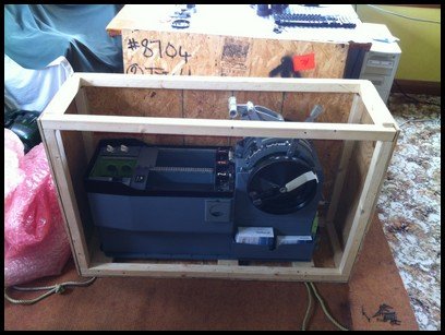
A big orange truck from TNT Express parked outside the house this afternoon and the driver began to offload a large wooden crate that weighed around 80 kilograms.  I could be only one thing – the Boeing throttle quadrant and avionics box (center pedistal) had finally arrived.   

Together, the driver and I manhandled the crate through the hallway of the house to the room in which construction of the simulator is taking place.  Removing a heavy piece of machinery from a wooden crate can be tricky, and the only method was to disassemble the box screw by screw – WOW what beauty!

Initial Thoughts

The throttle and avionics bay is a genuine aircraft part so there wasn’t much to not like; you can’t “immerse” yourself or get a more authentic experience than by using a real aircraft part.  The throttle originally was in use in a Boeing 737-300 with South West livery.  Unfortunately, the guy at the tear down yard didn’t document the tail number of the aircraft it was removed from.  It would have been nice to have a photo of the actual aircraft to place on the Blog.

The first aspect I noticed about the throttle was the build.  It’s a solid piece of engineering built to withstand the neglect of pilot use and now simulator use.  I don’t believe the throttle will ever be damaged from neglect my end – its’ solidly constructed.  The feel when you push the two power levers forward is - well – you just have to be here!  Manoeuvring the flap lever through the various indents is equally rewarding.  Knowing that the throttle was once used in a real aircraft by real pilots adds a completely new dimension to flight simulation.

Retrofitting and Connectivity

During the refurbishment of the throttle, I had decided to not bastardize the throttle to try and replicate the appearance a throttle from a Boeing NG.  Therefore, the throttle remains a 300 series throttle.  It has been repainted only where necessary and decals have been replaced only when they were unreadable.  The internal mechanism of the throttle has been completely striped, cleaned and serviced.  Parts, such as the huge cog wheels and unnecessary internal wiring have been discarded as these are not required for simulation use. 

To allow the throttle to connect correctly with flight simulator, three Phidget cards (0066 & 0064) & a Leo Bodnar card (BUO 836X) have been used.  The cards are connected directly to the front of the throttle casing and will not be visible once the throttle casing is connected to the centre stage of the main instrument panel (MIP). 

All the functions of the throttle operate with the exception of the stab trim switches, which can be linked to another FS function if required.  Trim wheels are functional with the use of a servo motor and the trim spins when electric trim is activated on the yoke.  Back lighting is integrated back lighting (IBL) using genuine Boeing 5 volt bulbs.

oem 737-300 throttle quadrant - initial thoughts: it’s built like a thunderbox

Current Status

At the moment I’ve only taken delivery and am in the process of connecting a Benchmark card to an external power source to allow power to reach the 5 volt lighting bulbs and servo motors.  I have little doubt that there will be teething issues with software as I configure everything for correct functionality, but I believe that this extra effort is worthwhile to be able to use a real throttle instead of a replica.

Center Pedestal

The avionics bay is a two-bay type.  Two-bay types were mainly used on the earlier Boeing classic series jets up to the 200 series, however, a number of 300 series aircraft used them as well as 400 series.  The bay was attached to the throttle when I bought it, so rather than dump it and replicate a NG three-bay; I’ve decided to use it to maintain authenticity.  I may at some stage in the future replace it with three-bay – I’ll see how things develop once I begin to populate the bay with avionics instruments.  One benefit of using a two-bay style is that once Weber seats are fitted to the flight deck there will be more room to squeeze past to get into the seat!

An interesting feature to the unit is the positioning of two oddly shaped aluminium pull downs.  At first, I had no idea what these were used for.  Then it dawned on me – they are retractable coffee cup holders.  What more can you ask for (laughing). 

oem 737-300 fire suppression panel

Fire Suppression Panel (FSP)

The fire suppression module was an afterthought.  A second hand unit was available and I decided to retrofit this with limited functionality to flight simulator.  At the moment IBL works, and when pulled, each fire handle does what it’s supposed to do.  At some stage in the future I may activate the fire bell.  But, at the moment it’s early days with regard to this.  Basically it’s a module that has to be installed into the avionics bay for aesthetics; a TQ without a fire suppression module looks a slightly naked.

More on the actual avionics bay at a later stage when I begin to populate the bay with instruments - much kmore interesting than looking at "naked bay"