Using Genuine B737 Aviation Parts

A colleague grinding the tails from genuine DZUS fasteners. These will then be attached to reproduction modules to enhance their appearance

There is something fundamentally different when using a genuine piece of aircraft equipment instead of a replicated item – It’s difficult to define, but the idea of using a piece of hardware that flew thousands of flight hours, in good and bad weather, has a certain appeal.

You will notice when you peruse the below list that many parts are not Next Generation, but are from classic 737 airframes, Finding Next Generation components is time consuming and can have long lead times. In the interim, I am using classic parts as fillers. Fortunately, some components used in the classics, especially the 737-500 are also used in the Next Generation.

The following OEM parts are currently used and converted:

  • 737-500 yokes and columns (2)

  • 737 Captain-side stick shaker

  • 737-300 throttle quadrant

  • 737-300 telephone and microphone

  • Jetliner style aviation headset (was formally used in an United B737)

  • 737-300 three-bay center pedestal

  • 737-400 fire suppression panel

  • 737 yoke trip indicators (2)

  • 737 rudder pedals (2)

  • 737-500 audio control panels (2)

  • 737 Weber captain and first officer seats

  • MD-80 clock (flight officer side of MIP)

  • 737 overhead map light

  • 737 korry switches

  • 737-500 tiller handle

  • 737-300 Forward & Aft Overhead Panel w/ Coles engine switches & genuine light switches

  • DZUS fasteners

  • 737-800 flap guage

  • 737-800 Yaw Dampener gauge

  • 737-800 brake pressure gauge

I would like very much like to replace the ADF and NAV modules with OEM panels; however, need to research the feasibility in doing this.  In the meantime, I’m using reproduction navigation radios manufactured by Flight Deck Solutions.

Historical Significance

The historical significance of using genuine parts cannot be ignored.    It’s relatively easy to research an aircraft frame number or registration number and in the process learn where the aircraft was used and in what conditions.  

For example, the throttle unit I am using was removed from a South West B737-300 that plied the continental USA for many years, whilst the yokes and columns were previously used in a B737-500 operated by Croatian Airlines.  The clock I have for the flight officer side of the MIP came from a FedEx MD80 and one of the ACP units was used by Aloha Airlines in Hawaii.

Recycling

Using OEM used parts helps the environment!  

For a start, you are not purchasing new reproduction parts made from virgin resources.  Secondly, the used parts you bought probably would have been destined for expensive recycling, or alternatively disposed of to landfill.  

Recycling can be fun!!  

It’s a good feeling to convert something destined for disposal and bring it back to life.

Toughness

One of the major benefits of using OEM aircraft parts is their longevity and ruggedness.  Whilst none of us want to damage our simulators through over zealous use; it can and does occur from time to time.  Replica parts are – well a little delicate.  To ensure long life you must treat them with care.  

It’s the opposite with genuine aircraft parts; damaging a genuine part with normal use is almost impossible.  

For example, a speed brake lever is relatively easy to bend or break on any number of replica throttle quadrants on the market; damaging a genuine speed brake handle is very difficult as they are constructed from high grade materials to withstand genuine stresses (pilot-driven or otherwise).

Simulation pilots are often as rough on their gear as genuine pilots are; I’ve seen simmers jab ACP buttons with enough force to break a piece of plastic.  Genuine buttons are made to withstand this heavy-handed treatment, replica parts – break!

Aesthetics – Look Your Best

It’s a fact; aN oem aircraft part looks 100% more realistic than a simulated part – that’s obvious.  If your center pedestal has an assortment of genuine modules mixed in with replica modules, the pedestal will appear much more authentic than one comprised solely of simulated units.

You will be surprised that small things can make a huge aesthetic difference.  Take for example, DZUS fasteners.  I bought a box of fasteners sometime back and use them wherever I can to replace the reproduction fasteners or screws that many manufacturer’s use.  If the fastener does not fit the appropriate hole in the reproduction module, I either enlarge the hole with a drill bit, or if this isn’t feasible, I cut the tail from the fastener leaving only the DZUS head.  I then use a piece of sticky blue tack or crazy glue to secure the DZUS head to the appropriate part.  

OEM B737-300 two-bay center pedestal showing mix of reproduction and oem components

The fasteners I've used were purchased second-hand; therefore, they show wear and tear.  I don’t mind this used and abused look.  Yes it sounds rough and ready, but the end result looks very pleasing to the eye and more faithful to what you would see in an operational flight deck.

The confines of the flight deck are not as clean as one might expect, and instruments are scratched and dented; pilots rarely concern themselves with aesthetics and technicians complete their maintenance quickly, as an aircraft not flying equates to lost revenue for the airline.

The use of genuine parts adds to the immersion factor, and as a Dutch simmer recently commented: “It makes the simulator more alive”

Availability of Parts

oem aircraft parts can be difficult to find and it’s a hit and miss affair.  As newer aircraft are brought online, airlines scrap their older fleet and parts become readily available.   

Finding late model Next Generation parts, at a reasonable price is almost impossible; these parts are still serviceable.  Parts in older aircraft may also be serviceable; however, they must meet safety regulations and be inspected and approved by a certified agency.  This process is expensive and many airlines find it cost prohibitive; therefore, parts are sold as scrap.

E-Bay can be a good place to find parts.  Search for aviation parts - Boeing, 737 or Gables.  Aviation scrap yards are also invaluable, as are the classified sections in various flight simulation forums on the Internet such as My Cockpit and Cockpit Builders.

Conversion - Use in Flight Simulator

This can be minefield to the uninitiated.

OEM parts often operate on a variety of voltages, and it’s not uncommon to need 5, 12, 18 and 24 Volt power supplies to enable an OEM part to work correctly.  Further, the wiring inside the neat-looking box can be a rat’s nest of thin wires weaving their way to and from a variety of unidentified pieces, before terminating in an electrical connection rarely found outside the aviation industry (Canon plug).

I am not an expert in conversions (although I am learning quickly.....).  I’m lucky in that I have access to a few people who are very knowledgeable in this area and are happy to share their knowledge with me.  

Interfacing

There are a number of ways to interface an OEM part with flight simulator.  The easiest is to use is a Leo Bodnar BU0836 joystick card, or similar, using standard flight simulator commands and/or FSUIPC.  The use of these cards makes assigning functionality in flight simulator very easy and straightforward.

One BU0836 card provides 12 inputs which correlates to 12 individual switches or buttons.  The 0836 card also has the capability to have a matrix constructed which increases the number of available outputs.  Another joystick card that is very good and easy to configure is the PoKeys card.

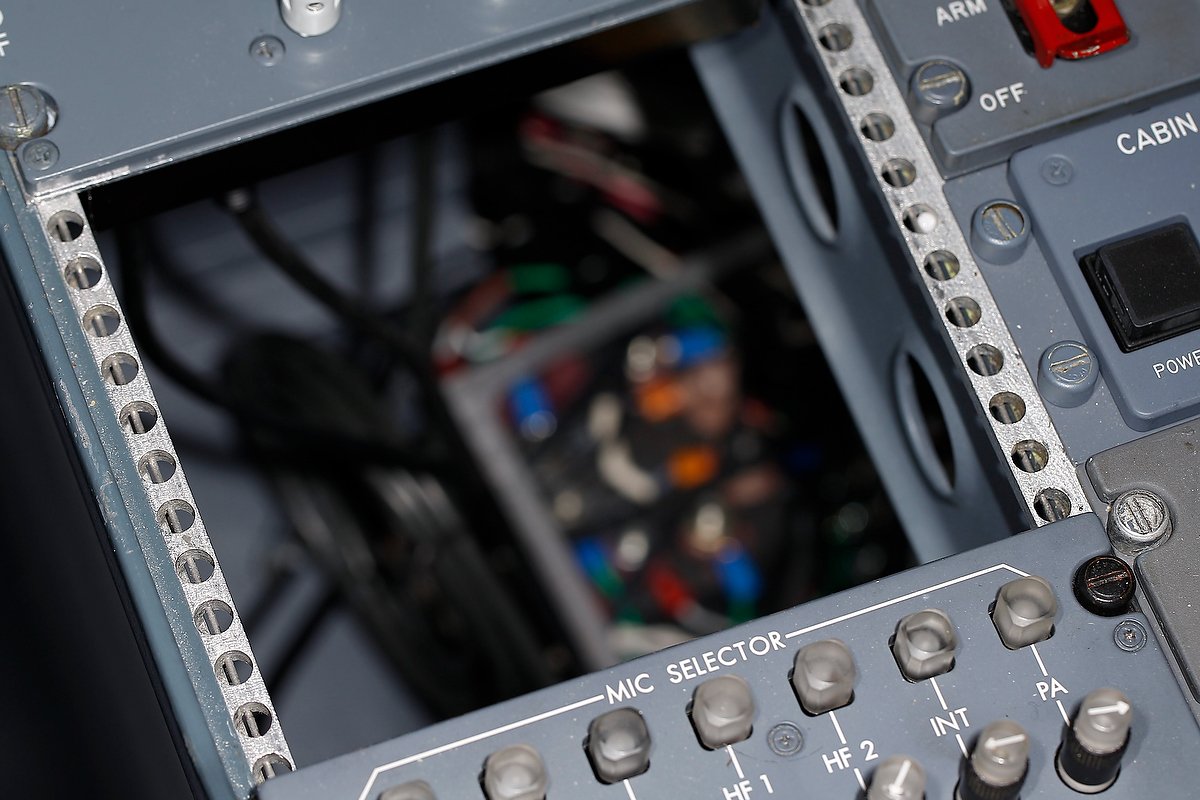
The inside of a 737-500 ACP module showing the rat’s nest of wiring that can be found within an OEM module

For functionality that requires movement, a servo motor will need to be used and configured in FS2Phidgets.  Phidgets allow you to program almost any moving part, such as the needle of the rudder trim module or the trim wheels of a throttle unit.    Digital servos are better than analogue servos as the former do not make an audible squeaking noise when connected to power.

By far, the most difficult part of any conversion is discovering what wire connects to what functionality.  Finding the wire can be challenging in itself as most avionics modules are a nest of wires, diodes and electronic circuitry.

You Have A Choice

You don’t have to use reproduction simulator parts throughout your flight deck – there is a wide selection of used aviation parts available, and with a little searching, you probably can find what you want.  

OEM parts frequently can be found at far less cost than their reproduction counterparts, and in every case will always look more visually appealing.  If you’re not up to the task of conversion, there are individuals that can convert modules for you.  You will then need to configure the functionality in FSUIPC or directly in the avionics suite used.  At the very minimum, using DZUS fasteners will bring your simulator to the next level of realism.  But be warned, using OEM parts evokes a desire to replace anything replica with something real.

In my next post we will look at converting two genuine B737 Audio Control Panels (ACPs) to flight simulator use.

Throttle Thrust Problem - Loosing Thrust at N1 - The Solution

oem 737-300 throttle

The throttle installed into the simulator is a converted genuine B737-300 throttle.  Lately, I have observed inconsistent power thrust issues during the take off roll and climb out. 

As I begin the take off roll, engage TO/GA and rotate, but before acceleration altitude or acceleration height is reached, one of the throttles looses or gains power.  Moving the throttle handle reinstates throttle power, but the power is dependent on where the actual throttle lever is physically positioned. 

When the aircraft is above thrust reduction altitude (1500 radio altitude) the problem rectifies itself.  The problem cannot be replicated when flying above 1500 feet.  I also noted, and this may also be part of the issue, that the power indicators located on the EICAS display fluctuate (twitch) a little as I moved the throttle levers.

This problem only began to occur after I transferred the avionics software to ProSim737.

Process of Elimination

Problems like this are not uncommon when interfacing real aircraft parts and the challenge is finding the cause of the problem.  The only method to determine solutions to problems such as this is to systematically, through the process of elimination, identify the problem area.

My first thought was that one of the potentiometers in the throttle quadrant maybe damaged, although I considered this to be unlikely as the units are still relatively new.  The throttle has four potentiometers: throttle 1, throttle 2, flaps and spoilers. Flight testing indicated that the power loss alternated between engine 1 and engine 2; therefore, the likelihood of two potentiometers failing at the same time was minimal. 

The next step involved checking the wiring within the throttle quadrant, to ensure there wasn’t damage to the outer coating of the wires.  A damaged or loose wire can easily short on the throttle frame and generate a spike.  However, if the wiring was loose or damaged, the problem would also occur when flying at altitude, and I had clearly demonstrated that the problem only occurred during the take off roll and climb out to thrust reduction altitude. 

The next step was to ensure that calibration of the throttle unit was correct.

Re-Calibration Using FSUIPC

I decided to re-calibrate the throttles using FSUIPC rather than FSX.  This process isn’t difficult and FSUIPC allows you to fine tune each throttle with greater accuracy than is possible with FSX. 

After re-calibration, the “twitching” of the power indicators ceased, but the initial problem remained.

The Cause of the Problem

The only culprit I could think of to cause this problem was ProSim737.

To check whether ProSim737 was actually the cause of the problem, it is necessary to remove any input from the ProSim737 software.  This is straightforward.  Either use another avionics software package or use FSX itself.  I did twenty trial flights using both Sim Avionics and FSX and the problem did not replicate. 

ProSim737 Excellent Support and Advice

I contacted the developers at ProSim737 explaining my problem in detail, and I received a response to my questions within a few hours.  Marty was especially helpful and we discussed several potential reasons for this issue and possible workarounds.  I must stress that the response I received from ProSim737 was absolutely 100% top notch. 

Marty genuinely wanted to help resolve the issue – whether it be with ProSim737 or otherwise.

Real B737 Throttle Operation

Now this where the comment “as real as it gets” does have meaning…. 

The developers of ProSim737 have designed their software to replicate the logic used by the real B737 auto throttle.  The software (ProSim737) is doing exactly what it’s supposed to do in relation to power thrust, and the issue I was experienced is caused by using a real aircraft throttle without automation.  Let me explain.

In the real aircraft, when TO/GA is enabled, the auto throttle logic has control of the aircraft.  The throttles are off-line and power thrust cannot be manipulated by the pilot.  The flight mode annunciator (FMA) illuminates N1. 

As 84 knots is passed the FMA changes from N1 to THR HOLD.  At this time, the actual throttles come back on-line, meaning that you can manually alter throttle power by moving the levers.  After rotation and at 800 radio altitude the auto throttle system is ready to change from take off power to climb power and the FMA changes from THR to ARM.  When in ARM mode the throttles are still on-line. 

When the aircraft reaches 1500 RA which is the thrust reduction altitude, the throttles go off-line and the AT logic is controlling the power thrust of the throttles.  The FMA changes from ARM to N1.

Throttle Anomaly

The B737 does not have a manual throttle, but an automated throttle.  The software is programmed to move the throttle levers to the correct position mimicking the actual power thrust called for by the auto throttle logic.

If you use a manual throttle (genuine or otherwise) the connection to the automated physical movement of the throttle levers is missing; you must counter this by moving the levers yourself.  This issue should not occur with a correctly calibrated automated throttle.

Using an Auto-throttle

If you have an auto throttle, the levers will automatically and physically move to the indicated thrust position as determined by the auto throttle logic (90%N1 at TO/GA).  When the FMA illuminates THR HOLD at 84 knots, and the throttles come back on-line for possible pilot intervention, the auto throttle logic will not sense any change in the throttle lever position, and power thrust (90%N1) will be maintained.   This is because the automated system placed the throttle levers in the correct position when TO/GA was initiated.

Using as Manual Throttle

However, if you’re using a manual throttle, the throttle levers MUST be physically positioned at the correct location on the throttle quadrant, otherwise the auto throttle logic will sense a change in position of the levers and alter the power thrust accordingly to this new level. 

This is what was occurring in my situation.  I was resting my hand on the throttle and only advancing the levers 3/4 of the way forward.  TO/GA indicated 90%N1, but when the throttles came on-line at 84 knots, the auto throttle logic noted that the position of the throttle levers was not at 90%N1 and subsequently altered the power thrust accordingly.

The reason the issue was inconsistent is that I didn’t always advance the throttle levers to the same position, and if I did the problem did not occur.

LEFT:  B737-300 throttle quadrant converted to Flight Simulator use.  The TQ is a manual throttle meaning that the thrust levers are not automated and must be moved manually.  I have used a pencil to lightly mark the metal adjacent to the most commonly used N1 settings.  This ensures the levers are moved the correct location during take off.  Lever position is set to 90%N1 and flaps 5.

Solution – Change in Procedures

The solution to this anomaly of using a real “manual” throttle is relatively simple.

You must determine where on the throttle quadrant the various N1 power settings are and then ensure, after engaged TO/GA that you move the throttle levers to the correct position (90%N1).  In my situation, the procedure is to advance the throttle to 40%N1, engage TO/GA, and then manually push the throttle levers to 90%N1.

Thank you

I’d like to thank Marty at ProSim737.  Marty worked with me to solve the issue, which ultimately was not really a problem with either ProSim737 or my set-up, but is an anomaly of using a genuine throttle unit without automation.

Possible Update

I may update the throttle quadrant to enable automation of the throttle levers and speed brake, however, for the time being the throttle quadrant will not include automation.

Update

on 2013-04-23 23:56 by FLAPS 2 APPROACH


diagram 1: a clear diagram that helps explain the problem discussed in the article (thanks to frazier @ prosim737 forum)


Telex Airman 750 Headset - Adding To Realism With Real Parts

oem telex 750 headset

To quieten some of the ambient sounds (dogs barking), I use a David Clark aviation headset (model H10 13-S) which is a left over from when I did my ]private pilots license (PPL).  This particular headset is a marvel of engineering and works exceptionally well for real world flying and simulator use.

Recently, I saw for sale in a wrecking yard, an airliner style Telex Airman 750 headset.  The price was $30.00 including freight from the USA to Australia.  To be honest, I wasn’t expecting too much – after all, what does one get for $30.00 these days!  I was pleasantly surprised when I opened the FEDEX sachet and an almost brand new headset, equipped with boom mike and tell-tail aviation style audio connectors and cable, fell onto the floor.  The foam ear pieces were still good condition, as was the small clip that attached the cable to your collar (to stop the cable from snagging).

After plugging in the headset to the Flight Sound X Adapter (click to see earlier review), I was even more surprised when the headset worked!  Sounds were crisp and easy to hear and the weight of the headset minimal.  The boom mike relayed my voice more than adequately across the network to VATSIM.

Using real aircraft parts adds to the realism of flight simulator; a headset being just one item.  I guess bargains still do exist.

Populating the B737 Center Pedestal

oem 7373400 center pedestal (two bay). avionics include cp flight, flight deck solution and oem. this pedestal has since been replaced with a three bay pedestal

The centre pedestal I’m using is a real aviation part procured from a South West 737-300 series aircraft. The pedestal came attached to the throttle quadrant and is the more uncommon two bay style. The Next Generation uses a three bay center pedestal.

I was reluctant to destroy a piece of aviation memorabilia, so rather than cut the pedestal from the throttle and discard it, I decided to keep the two bay pedestal and limit myself only to essential avionic modules.

Apart from the nostalgia of using an OEM pedestal, I really like the DZUS rails that are used in a OEM pedestal, which allow you to drop the various panels into place and secure them with a DZUS fastener.  To read about DZUS fasteners, navigate to my earlier post.

In this post I will discuss populating the center pedestal with panels, and touch on using the panels from a comparative newcomer - SISMO Solicones. I will also discuss some of the problems I had with installing reproduction panels to the OEM center pedestal.

No International Standard  - Variation

There is no international standard established to indicate which model/type avionics are installed in a center pedestal; more often than not, it will come down to the type of aircraft and a particular airline’s requirements.  Early series 737s were fitted with a two bay center pedestal which minimised the number of panels that could be fitted.  Later model 737 aircraft and the Next Generation aircraft series use a three bay center pedestal that enables installation of the latest navigation and communication equipment.  There are benefits to the thinner two bay pedestals, the main positive being more room to climb into the flightdeck.

All 737s will have as a minimum the following avionics installed:  Fire Suppression module, NAV1/2 COMS 1/2, ADF 1/2, audio, rudder trim and transponder.  The important modules will be duplicated for First Officer use and redundancy should a failure occur.  Depending upon the aircraft series, the following may also be installed: thermal printer, HUD set-up, radar, cargo door panel & floodlight switches, alternate communications, etc, etc (the list is almost endless).  Much of what is installed depends on the use of the aircraft, civil regulations in the country of use and the requirement of the particular airlines.

Module Location

As with colour, there is no standardization to the location within the pedestal for any particular panel - perhaps with the exception of the fire suppression panel and NAV 1/2 module which (usually) occupy the forward part of the center pedestal.  Modules are fitted wherever they fit and in line with whatever specification that the airlines requires.  For example, I have observed Audio Control Panels (ACP) mounted toward the rear of the pedestal, which I believe is the favoured position, and also towards to front of the pedestal.

Another interesting aspect to observe is the different knobs on the NAV and ADF radios.  Often simmers became mentally entangled in attempting to standardise everything across their simulator.  This is not necessary; it is realistic if you mix-match panels to a certain degree.

The center pedestal is populated with the following modules:

  • NAV-1 (Flight Deck Solutions)

  • NAV-2 (Flight Deck Solutions)

  • M-COMM (Flight Deck Solutions) new style module that incorporates all radios in one module

  • ADF-1 (CP Flight) - replaced with Flight Deck Solutions.

  • ADF-2 (CP Flight) - replaced with Flight Deck Solutions.

  • Rudder Trim (CP Flight) - replaced with OEM.

  • ATC (transponder) (CP Flight) - replaced with OEM.

  • Fire Suppression Module (OEM 737-400 converted for FS use) - replaced with 737-600 NG.

  • Audio Control Panel (2) (ACP) (OEM 737-400 unit – at the moment, wired only for backlighting)

Avionics Mania

Unless you have an unlimited budget, or have panel sickness, you may want to think about how often you will use a particular panel.  Navigation (NAV 1/2 & ADF 1/2) and communication (COM1/2) modules will be used on every flight; therefore, it’s best to purchase a high-end panel for consistency and reliability. 

The rudder trim module and Audio Control Panel (ACP) are rarely used, with the exception of engine out operations and for turning on/off the audio for the various navigational aids. 

This is a side benefit to using a two bay center pedestal:  there is only so much room available, so you are forced to decide on which panels take precedence over others.

Maintaining Brands – almost impossible

I had wanted to maintain the same brand of modules across the sim to minimise the number of different system cards and interfaces, however, this was difficult to do. 

Flight Deck Solutions, a premium upper shelf supplier of simulation parts to the professional and enthusiast market, do not at the time of writing, manufacture and sell an ADF navigation radio panel.   Further, FDS do not produce the older style ATC (transponder) panel; they only manufacture the newer push button type, and I favoured the older style.

As the MCP I am using is manufactured from CP Flight, and I also have an older style CP Flight transducer, I decided to opt for the CP Flight ADF navigation radios. CP Flight have an easy method to daisy chain panels together. Unfortunately due to supply issues this was not to be the case.

OEM Panels

Nothing beats OEM panels and I am hoping in time to replace many of the reproduction panels with OEM components. In the meantime, I will be using reproduction panels.

SISMO Solicones

A relative newcomer to the scene attracted my attention – a Spanish company called SISMO Solicones.  Their products are reasonable quality for the price paid, are 1:1 ratio to OEM panels, use Ethernet rather than USB, and relatively easy to configure. 

I was very keen to trial Ethernet as a method to connect the modules to the computer. 

SISMO SOLICONES. Note the electronics tab that needs to clear the DZUS rails for installation.  A poor panel design if using an OEM center pedestal

Module Size – Size Matters!

It’s very important to check that the panel will fit correctly to whatever pedestal you are using.  If you are building your own pedestal without rails, then this is not an issue as you can easily fashion a template to drop the panels into.  However, if you are using an OEM panel, you will need to ensure that the panels are built in such a way that they drop into the existing rail system in the pedestal, otherwise you may need to alter your rails.

ADF Navigation Radio Panels – Attaching to the DZUS Rails

The avionics panels made by Flight Deck Solutions are literally drop & forget as all FDS panels are DZUS compliant and fit OEM DZUS rails perfectly.  The ADF radios from SISMO are a different matter.  Each of the panels has a small tab on the electronics board which is too wide to navigate past the DZUS rail in the pedestal.  This is a major issue as the panel cannot be dropped onto the rails.  Why SISMO designed them this way is beyond me, as many serious simmers use OEM center pedestals.

Cutting the Rail – Delicate Operation

Although I was reluctant to cut the DZUS rail, I realized that this was the only method available to correctly fit the SISMO ADF panels.  The rail had to be cut and a portion removed that corresponded to the size of the tab. Removing a portion of the rail would allow the panel to then be dropped into the pedestal. 

OEM 737-300 CENTER PEDESTAL WITH RAIL CUT TO ENABLE REPRODUCTION PANEL TO BE INSTALLED

The DZUS rails are attached at regular intervals to the inner side of the pedestal by several aluminium rivets.  The rivets are not moveable and unfortunately a rivet was located directly where the rail was to be cut. 

After triple checking the measurements, I used a dremel power tool and small metal saw to gently cut into the aluminium rail until flush against the edge of the pedestal.  The cut piece of aluminium rail then was able to be removed; however, the rivet body remained.  I then used a metal file to carefully grind away the end of the rivet head until flush with the pedestal side. 

In addition to this, each of the attachment holes of the panelss needed to be enlarged slightly to accommodate the male end of the OEM DZUS fastener.  This job was relatively easy and I used a quality drill bit to enlarge the hole.  A word of caution here – SISMO do not use metal backing plates, so if you’re over zealous with a drill, you will probably crack the plastic board.

Once the sections of DZUS rails were removed, it was only a matter of dropping the panels into the pedestal and securing them with DZUS fasteners.

SISMO SOLICONES rudder trim and ADF module with power pack.  The rudder trim is A MEDIOCRE reproduction of the real unit. however, it lacks finesse in its final construction. I DO NOT RECOMMEND USING THESE PANELS

System Cards & Wiring – Location, Mounting & Access

I was very surprised at the number of cards required to use SISMO panels.  An Ethernet card is required as is a daughter and servo card.  There are also two power sources: 5 volt powers the small servo moto) that moves the rudder trim gauge and 12 volts powers the module backlighting. 

My main concern was where to mount the cards.  Initially, I was going to mount them under the main simulator platform, but access for maintenance was a problem. I decided to utilise the inside of the pedestal beneath the modules.  This area is rather cavernous and a good place to house the cards and wiring needed for the modules (out of sight and out of mind).

Constructing an Internal Board – to attach cards to

I cut a piece of thin MDF board to roughly the height of the pedestal interior and fitted it in such a way that it created a vertical partition.  To this board, using both sides, I attached the various cards needed.  To ensure that the flat cables had enough room to reach the various cards, I cut a slot in the center section of the board.  I also made sure there was enough room at each end of the board to allow cabling to snake around the partition. The most important point to remember is to ensure that none of the cards touch the metal sides of the pedestal or each other; to do so will cause an earthing problem. 

Wiring wasn’t much of an issue, as SISMO supplies prefabricated flat wiring with plastic clips.  All you need to do to attach the correct clips to correct attachment point on the card – very easy with absolutely no soldering.  As the Ethernet card is mounted within the pedestal, the only wires that need to be threaded through the lower throttle section of the pedestal are the power cable and the Ethernet cable.  The later connects to the Ethernet switch box that is mounted to the shelf of the FDS MIP.

The pedestal innards are now full of intestinal-looking wires attached to an assortment of cards.  It looks messy with all the wiring, but as the wires are flat wires with solid connectors, it is very secure and logically set out.  Access to the wiring and cards is achieved by removing two or three modules. 

Update

on 2012-07-25 05:48 by FLAPS 2 APPROACH

After trialling the panels manufactured by SISMO, I wasn't impressed.  The ADF navigation radio gave spurious results which were intermittent, and the frequency change switch did not provide consistent operation - sometimes it worked and at other times it was sticky and needed to pressed a few times to initiate the frequency change.

The rudder trim module also did not work correctly, even with the correct SC Pascal script. 

The Transponder ATC module looked OK, but never worked as a script was not supplied.  The Audio Control Module looked absolutely awful with poor quality switches and cheap and nasty-looking plastic buttons.

Rather than fight with cards, wires, and a software medium (SC Pascal scripts) which I don't have the knowledge to edit, I decided to box everything and send it back to SISMO for refund.

The SISMO panels have been replaced with panels made by CP Flight and OEM panels.

737-300 Telephone & Microphone for 737-300 Center Pedestal

737-300 internal communications

I have installed to the rear of the center pedestal the correct telephone and microphone for the 737-300 aircraft.  Neither item is necessary, but it adds to aesthetics and fills the empty gap where the telephone should have been installed.  Although the telephone and microphone are functional, they have not been configured to operate with the avionics suite or flight simulator.

The center pedestal and telephone are not from a 737-800 aircraft, nor would they ever be seen on a Next Generation aircraft; they fill a gap until the respective OEM components can be found.

Sometimes it’s a matter of what is available, or waiting until a part becomes available. In this case, I decided to use what was available.

This type of telephone and microphone (as well as other types depending upon manufacture) were used on the 737-300 through to the 737-500 aircraft.

As you can see from the photograph, this telephone has been there and done that!  The telephone is considerably scratched, but I prefer using part that shows service, rather than using a shinny new reproduction item.

Main Instrument Panel (MIP) by Flight Deck Solutions - Review


Overview

The main instrument panel (MIP) is arguably one of the most important pieces of equipment in a flight deck; it is around the MIP that everything revolves.  Every enthusiast wants the MIP to be athletically pleasing and as real to the OEM product as possible.  Depending upon the end use, the MIP may act as a skeleton from which to add OEM parts, or standalone accommodating reproduction parts.

There are several companies that produce MIPS and each has its nuances.  After extensive research, Flight Deck Solutions (FDS) in Canada was commissioned to supply the MIP.

Note that in this review, reference is made to the term OEM which is an acronym for Original Equipment Manufacturer (aka real Boeing 737 aviation part).

The image above is the Duel Seat Training Device offered by Flight Deck Solutions (image courtesy and copyright FDS).

Information - Not Pretty Pictures

This post is not intended to be an exhaustive review of the FDS MIP or the parts attached to the MIP.  Rather, the intent of the review is to provide adequate information for enthusiasts to make an intelligent decision to which MIP to purchase.  

Furthermore, it is important to understand that all reproduction simulator parts are exactly that - a reproduction or facsimile of a real part.  Often reproduction parts are not to scale and have subtle differences to the real item.  Whether this is important is at your discretion and very much depends upon whether you intend to use OEM parts or solely reproduction parts.

To view images of the MIP, navigate to the image gallery

Interface cards have not been discussed for two reasons.  First, there are several differing types of cards that can be used, and second, Integrated Cockpit Systems (ICS) units come ready-made with all wiring and interface cards installed. 

ICS and Options

FDS provide two options when purchasing their MIP - naked (do it yourself) or as an integrated cockpit system (ICS).

The ICS route was chosen because of time constraints; by eliminated the task of wiring and soldering a multitude of interrelated electronic parts together, it would allow more time to concentrate on converting real aircraft parts to use in the simulator.  At the forefront of the B737 project, the MIP was to be a skeleton from which to hang OEM parts.

The MIP consists of two sections; the main instrument display including the lower display and glare shields (eyebrows), and the base structure incorporating the CDU mounting area, lower display and stand.

FDS landing gear lever is a good facsimile of the real lever; however, the lever does not recess between the two half moons.  Nor is the red trigger spring-loaded as in the OEM mechanism.  Despite these aesthetic shortfalls, the landing gear functions well.  The leather skirt is a step in the right direction concerning authenticity

UPPER MIP (Instrument Panel, Glareshield and Lower Panel/Kick Stand)

The panel is made from CNC machined acrylic and the glare shield from injection molded plastic. The panel and glare shields have been attached by screws to a light-weight powder coated aluminum frame which incorporates a 4 inch wide shelf on the rear side. 

The cut-out lettering, which allows the lettering to be back-lit, is very crisp with well defined edges.

The panel has been professionally painted in Boeing grey.  Although the panel is made from acrylic, the use of high quality flat paint removes the sheen that acrylic is renowned for.  In comparison to other plastic-looking panels on the market, the colour and appearance is very true to form.  It looks 'almost; like the OEM panel. and matches the real aircraft parts very well.  Furthermore, FDS apply the paint in several thin layers which makes the coating very resistant to chipping and scratching.

Switches have been mounted in the correct locations and the wiring from these switches has been secured within a wiring lumen or by plastic cable ties.  The switches and knobs replicate those of the real aircraft and have the correct feel, although the general purpose knobs (GPK) do not replicate the exact appearance of the OEM knob.  Where a panel has not been included (not stock B737 configurations) a blanking panel has been fitted.

The soldering work and connections on all switches are excellent; it is more than obvious that the person who did the soldering work is a professional with many years experience.

The gear lever is sturdy and feels solid.  To engage the landing gear, the lever must be pulled out of its recess and pushed up or down.  The detail to the lever is excellent and installation includes the correct-looking fiber sleeve.  The mechanism does not have the spring-loaded trigger; the trigger is a solid cast item attached to the lever.

Annunciator lights (six packs) and various warning lights are all functional; however, pale comparison to OEM parts and other high-end reproductions; they appear 'cheesy'.  The glare shield is strong textured ABS plastic and wraps over the top of the MIP.  A correctly sized chart pocket is screwed to the top of the shield.  The two glares either side of the MIP on the Captain and First Officer side are painted MDF wood and although not have a negative appearance they do not replicate the appearance of the OEM glare which is made from textured foam plastic.

The shelf system, located behind the main instrument panel, is an excellent idea.  The shelf, in addition to providing an area for the FDS monitor stands to be mounted, is a good platform to mount various cards, speakers and other items that may be required.

The FDS bracket, a novel design to hold the display units firmly in place.  The display unit bezel is made from plastic and does not hinge outwards as the real bezel does.  the knobs on the ISFD are not replicated

The lower display modules, which are mounted to the lower area of main panel, are installed using normal Phillips-head screws.  In a real B737, panels and modules are usually secured using DZUS  fasteners or skirted screws.  It would have been a nice touch to have replicated the use of DZUS fasteners on the panels in the lower kick stand.

Display Unit Covers

The protective displays that the computer monitor screens (display units) are made from 1.5 mm thick perspex.  I have found the perspex to be very reflective - especially so if the simulator is located in a well-illuminated room.    

Integrated Back-Lighting (IBL)

Integrated back Lighting (IBL) is the name FDS has coined to refer to their proprietary design in which FDS utilise aircraft bulbs rather than LEDs.  IBL is supplied to illuminate the back lighting in all FDS panels and modules.  

One of the main advantages of a bulb in contrast to that of a LED is the throw of the light and the colour temperature.  The area of coverage from bulbs is relatively even, where the coverage by an LED is more pinpoint and uneven.   The only way to achieve a similar light coverage to bulbs using LEDs is to use several LEDS mounted in close proximity to each other. 

One area that the use of bulbs  excels is the rear illumination of the stencil-cut lettering on the MIP.  Bulbs will completely illuminate the stencil cut-outs where LED lighting will often only illuminate part of the stencil cut-out (unless there are several LEDs).

Bulbs and LEDs have different colour temperatures.  A bulb transmits a warm colour (soft orange hue) whereby a LED transmits a cooler colour that appears more blue in comparison.

All Boeing airframes, with the exception of the newest airframes utilise 5 and 28 volt incandescent bulbs.

The only downside of IBL (if there is one) is that the bulbs generate quite a bit of heat.  The life of a bulb is also less than a LED.

Ground Proximity Panel showing use of Phillips head screws rather than the more usual DZUS fasteners

What the MIP Lacks

The non-use of DZUS fasteners in the lower panel (kick stand) and the failure to use skirted screws has been mentioned.

Stand-by instruments and clocks are not included.  FSD supply a stenciled backing card which is mounted behind the perspex to mimic the look of the yaw dampener, brake pressure, clock and flaps gauge. 

Considering the purchase price of a MIP, and considering the importance of a working flaps gauge, an operational analogue flaps gauge should be a stock item.  

The avionics suite (Sim Avionics) can display virtual stand-by instruments id required.

The speed reference panel and knobs are not functional. The knobs used in the speed reference panel do not replicate the OEM knobs used in the B737; the real aircraft uses double rotary encoder knobs. As with the flaps gauge, these knobs should be functional and, at least shoe some resemblance to the real part.

Software - Interface IT

The software to interface the MIP (InterfaceIT) seems to be well designed and robust.  It does require a learning curve to become proficent with the software, but once proficent the siftware is logical in layout and use.  Installation of the IT software is straightforward.
Additionally, there is a direct link between InterfaceIT and Sim Avionics which makes internal configuration and programming very easy.

Flight Avionics Suite

Duel Seat Training Devices (DSTD) and MIPS configured by Flight Deck Solutions use Sim Avionics as their flight avionics suite.  After you receive your MIP, FDS staff will e-mail to you a file which you import into InterfaceIT.  This file holds the data assignments for the MIP buttons and switches.

Although FDS recommend Sim Avionics, there is no obligation to use this software; the MIP will operate with whatever software you choose.  A seperate post will deal with a review of Sim Avionics.

The rear shelf located behind the MIP and the propriety bracket used to hold the display units (computer screens) firmly in place.  The bracket works exceptionally well and the shelf is very sturdy

Lower Base Structure

The base structure comprises the lower section of the MIP and includes the CDU bay structure and lower display screen.  The structure is made from aluminum which has been professionally powder coated in Boeing grey. 

As with the upper section of the MIP, the attention to detail is obvious.  There are no sharp edges on the CDU bay structure, nor are there gaps where panels attach together.  Screws match their holes correctly.

The DZUS rails that line the internal section of the CDU bay marry perfectly with the DZUS fasteners used to secure the Control Display Unit (CDU/FMC) to the rails.    It does not matter whether a reproduction or OEM CDU unit is used as both will fit perfectly.

The lower display screen, which fits between the two gaps in which the CDUs reside, is identical in shape and manufacture to the upper display unit bezels.  Unlike the three upper bezels in which a standard computer monitor can be mounted, the lower screen requires a smaller monitor which is not an off the shelf item.

clock panel showing backlighting during the day. the fabrication of this panel and button is very good as is the stenciling

Dimensions, 1:1 ratio and Using OEM Parts

The ability of a manufacturer to produce a MIP that is the correct 1:1 ratio to the real item cannot be underestimated.  If an enthusiast is intending to only use instruments and panels produced by that manufacturer, then any size disparity is probably unnoticeable and probably not that important.  However, if OEM parts are to replace reproduction parts, then the base sizing become crucial to the correct and easy fitment of an OEM part.  In this area, the FDS MIP has some shortfalls.

The MIP has a number of holes and gaps that parts reside, for example for the AFDS and flaps gauge.  If the holes are incorrectly matched to the OEM part, either a new panel (aluminum backing plate) will need to be engineered and painted, or the hole may need to be enlarged.  Although enlarging a hole in a MIP is straightforward, the opposite is problematic and requires the design of a new panel.

Unfortunately, many of the holes in the FDS MIP do not correspond to the correct size when fitting OEM parts.  For example, the holes that the AFDS units reside must to be enlarged considerably to enable OEM AFDS units to be fitted.  Likewise, the holes to fit the annunciators need to be enlarged.  The hole that the flaps gauge is housed is far too large and a new panel needs to be designed to gt an OEM flaps gauge.

Detail of the angled shelf used to accommodate the I/O cards.  The multi-voltage computer power supply can also be seen mounted behind the perforated vents.  The terminal block caters to 5 and 12 volts.  The interface card is the FDS SYS card which comes standard with the ICS MIP

Power, System I/O Cards and Cabling

A multi-voltage computer power pack is used to power the MIP and has been mounted at the rear of the lower base structure. 

The position chosen is well suited to internal wiring and allows easy access should a problem develop.

An angled shelf has been engineered to fit immediately behind the CDU bay.  The design of the shelf is intended as an area on which to mount the various interface cards required to operate the simulator.

The interface cards required to operate the MIP have been secured to the angled shelf and all wiring has been expertly soldered or attached via solid electrical clips.  Cabling and connections are of the highest quality.  Each of the wires that are connected to the SYS board has been tagged with a plastic tag which indicates their function; a good idea if you need to change something at a later date or troubleshoot a particular problem.

There has been no compromises with regard to how the staff at FDS wired the MIP - it is beyond reproach.

3mm replacement side stand.  The replacement stand inhibits any movement of the MIP as the structure is not (at the moment) installed within a shell

Base structure (side stands)

The base structure (stand) has been designed to be mounted either directly to a base platform.  The mounting points are numerous holes along the lower angled edge of the stand.  A concern was that the structure would wobble, as it is quite high and made from light-weight aluminum. 

These concerns were short-lived; once each attachment point was secured with a screw the assembly was quite solid.  This said, if you energetically engage the landing gear lever, there is a very slight movement in the upper area of the MIP.  If you are mounting the MIP into a cockpit surround, any movement will cease as it will be attached to the outer skin of the shell.

To counteract any movement, it is a relatively easy matter to fabricate two replacement side stands from a thicker sheet of aluminum (3-5mm).  This will guarantee that there will be no movement when manipulating knobs, the landing gear, etc.

Navigate to this post to read about the replacement side walls.

Communication, Support and Delivery

Communication with FDS was excellent.  E-mails were always answered in a timely manner and Peter and Steven Cos are very professional in their approach. I was continually kept in the loop regarding construction and shipping.

Support if and when required is either via a dedicated forum, e-mail, or if necessary by telephone.  Peter and Steve Cos very approachable and helpful and their support is second to none.  I would go so far as to say that the support that FDS provides cannot be matched.

It is important to note that Flight Deck Solutions is not a mail order company with products in storage waiting to be shipped; products are assembled to order.  This means that often there is a timely wait until you receive your shipment.

The MIP I had delivered to Australia was packed in and attached (screwed) to the floor of a large wooden crate.  It arrived undamaged.

Quick List - Pros and Cons

PROS

  • Well designed & constructed

  • Excellent workmanship (metalwork and wiring)

  • Realistic and highly effective Integrated Back-Lighting (IBL)

  • Good functionality

  • Very clean appearance - wiring and cards favorably positioned

  • 1:1 (or as near possible) to the real MIP (exception if using OEM gauges)

  • Moderate to high attention to detail

  • Robust & functional software (InterfaceIT) if using Sim Avionics avionics suite

  • Excellent paint quality (several layers of paint) that resists chipping and scratching

  • Outstanding support - the best in the industry

CONS

  • No analogue flaps gauge, other than virtual version (rectified by spending more money)

  • No stand-by instruments or clock (rectified by spending more money)

  • Non use of DZUS fasteners in lower panels above 'kick stand' (small things do make a difference)

  • RMI knobs are very low quality

  • Speed reference knobs are very low quality & do not replicate OEM B737 knobs

  • Landing gear lever does not recess behind shield when in down position

  • Landing gear does not utilise the spring trigger as in the real aircraft

  • Section between upper and lower MIP (kick-stand) is not the correct shape.  It should be rounded and not be an angled piece of aluminum

  • Display unit covers are very reflective (easily rectified- remove or replace them with tinted displays)

  • Slightly inaccurate General Purpose Knobs (GPK) - poor stenciling on knobs

  • The MIP is not completely 1:1 and if using OEM parts, some engineering is required to fit OEM parts

  • The MIP is not an exact reproduction and artistic license has been taken in some areas (for example, the section between the upper and lower MIP (kick-stand).  The MIP also lacks various screws and fasteners seen on the OEM MIP

Important Point:

  • If you are intending to add OEM panels, switches and knobs to the FDS MIP, be aware that many of the panels do not fit the FDS MIP.  This is because the MIP frame is not exactly 1:1 with the OEM equivalent.  In some instances (such as when retrofitting panels) the MIP is out by up to 1 cm.  Also be aware that OEM korrys, flaps gauges and some of other avionics will not fit into the precut holes.  You will need to either enlarge the hole or make it smaller.

FDS GPK with backlighting. The knob has a slightly different shape to OEM knobs. the adjustable propriety backlighting is perfect

General Purpose Knobs (GPK)

The GPKs are of high quality, however fail in a number of areas.

The black line is a manually applied adhesive which depending upon which knob you are inspecting, may or may not be quite straight.  Being adhesive, with time the transfer lifts, especially at the ends.  The translucent line between the black outer lines is not as bright as that observed in the real aircraft.  Not all knobs have the transfers correctly aligned.

poor quality lower kickstand knobs. gpk showing excess plastic from manufacture process

The knobs are the incorrect shape and the grub screws are located in the wrong position on the knob.  The knob also does not have an inside metal shroud (circular retainer).  The retainer increases the longevity of the knob as it stops the acrylic from being worn down over time with continual use.

The knobs on the lower kick stand are also of poor quality bearing only a little resemblance to the OEM knobs

The knobs serve a function, but for the price of the MIP, knobs that reflect a more accurate representation would have been appreciated.

fds adf knob. WHY EVEN HAVE THIS AS IT IS NOTHING LIKE THE OEM RMI KNOB

RMI Selector Knobs

The knobs are made from acrylic with a transfer attached.  The knob has no functionality and is attached to the MIP in a recessed hole.  The RMI knob bears no resemblance to the OEM knob and is very poor quality.

Speed reference knobs are very low quality

Speed Reference Knobs (SRK)

The speed reference knobs supplied with the FDS MIP bear no resemblance to the OEM knobs. The OEM knob should be a double rotary encoder knob.  There has been no attempt to replicate this type of knob.

Used Fuel Reset Switch

FDS have used a normal two-way toggle which is incorrect.  There is no similarity to the OEM used fuel reset switch.  The OEM toggle has a large bulbous head and is a specially-designed three-way toggle.

fds Boeing warning system. although functional the displays fall short of replicating the oem items

Autopilot Flight Director System (AFDS) 

Although not an exact replica of the OEM part, FDS has done a good job replicating the functionality of the AFDS.  Unfortunately, if you wish to replace the FDS unit with an OEM AFDS unit, the hole in the backing plate that attaches to the MIP will need to be enlarged considerably to allow correct fitting of the OEM component.

Boeing Warning System (six packs)

Compared to the OEM counterpart, FDS’s offering is lacking. The two warning buttons can be depressed very easily where the OEM buttons are quite firm requiring a good push. The six packs work quite well, however, lack adequate light coverage when a warning is displayed.

Annunciators (korry condition lights)

The FDS MIP uses LED reproduction annunciators (korrys).  The LEDS are illuminated by two 5 volt LED lights which do not provide complete light coverage across the lens plate.  The brightness of the LEDS is also not as bright as the OEM annunciators. 

Furthermore, the hole in the MIP that the korrys reside is a tad on the small side; therefore, if you are intending to replace the reproduction korrys with Original Equipment Manufacture (OEM) annunciators, you will need to engineer the hole to a larger size.  This is unfortunate as a MIP should be manufactured 1:1 to allow reproduction parts to be replaced with OEM parts.

on the oem landing gear the red trigger sits flush with the two half moons

Landing Gear Lever

The landing gear lever requires more explanation.

In the real B737-800 NG the landing gear handle sits closer toward the main instrument panel.  The half circular shield is designed so that the red-coloured gear trigger sits between the two half moon shields when the lever is in the DOWN position.  In the FDS version, the trigger sits too far out from the front of the MIP and the trigger is not protected by the two shields.

Furthermore, the trigger is not spring-loaded as in the OEM mechanism; it is a solid piece of metal.

Lights Test / DIM Switch

A normal two-way momentary toggle is used which is incorrect.  The OEM switch is a three way non-momentary switch which allows the switch to be placed in any one of three positions.  The OEM toggle is also large than a standard toggle switch.

Final Call

The MIP is well made and has been finished with obvious care; parts line up correctly, screw heads have not been burred and paint not chipped.  Wiring, soldering, parts, switches, paint, colour, rotaries, blanking panels and display frames are of the highest quality.  It is obvious you are dealing with a premium product that provides an very good facsimile of a 737-800 instrument panel.

Downside is the lack of any hard-wired gauges, poor quality speed reference and general purpose knobs, lack of DZUS in lower panels, no flaps gauge, and a wrongly positioned landing gear lever (when in the down position).  Another issue is that the MIP is not 1:1 with its OEM counterpart, nor is it a 100% accurate rendition of an OEM MIP. 

This said, for many enthusiasts this will not be an issue as the differences are minor.  If you intend to use OEM parts then some parts of the MIP will need to be fabricated to enable the real parts to fit snugly into the MIP.

Depending upon your end use - a MIP with reproduction gauges, or a MIP skeleton to hang OEM parts - your views will alter.  Certainly, the FDS MIP is not to be discounted as a premium product; it is a pity that FDS did not take a few extra steps to make this MIP the 'Queen of the crop.

The closest rival to the FDS MIP is the MIP manufactured by Fly Engravity and SimWorld.  Other MIPS are available from other companies, but the FDS MIP, although lacking in some areas is superior in many ways. 

Rating is 7.5/10

Please note that this review is my opinion only..  Furthermore, note the date of the review.   Flight Deck Solutions may have updated their MIP after this review has been published. 

  • Thanks to Peter Cos, Flight Deck Solutions for allowing the use of the front image.

NOTE:  Before taking what you read as gospel, check the FDS website in case these shortcomings have been rectified since this post was published.

Video - Weber Pilot Seat Adjustment Capabilities

A short video clip to follow up on the installation of two 737 Weber pilot seats (Captain and First Officer) that have been installed into the simulator. The seats were retrieved from a South West 737-400 that was destined for the wrecking yard. This video demonstrates the various positions that the seat can be adjusted.

To read additional information on the seats, see these other Journal entries.


Video - Operational Trim Wheels & Indicators

Now that the throttle quadrant is operational, USB hubs working and the Phidgets correctly configured, I thought I’d post a short video clip showing the trim wheel operation.  The wheel spin is controlled by inputs either from the auto pilot or from electric trim switches located on the yoke.  When the wheels spin, there is corresponding movement of the trim wheel indicator tabs; the indicators, which are coloured white show the pitch of the aircraft.

Currently, the trim wheels spin at only one speed (mono-speed adjustable in the Phidget settings).  Later on, when I have time I'll be altering the speed to variable-speed  This will allow the wheels to spin at differing speeds dependent upon whether the aircraft is being controlled manually or by the autopilot.  This configuration requires some extra time with Phidgets and is not essential at the present time.

The trim wheels are connected to a 12 volt DC servo motor.  The motor is mounted inside the throttle quadrant near the actual wheels. To control the power to the servo motor I have used a Phidget advanced servo motor controller.  Double click video to view full screen.


Safety First

The trim wheels have a white line painted on them for a very good reason (not invasion markings for D-Day 1944).  The spinning wheels are dangerous – keep your fingers well away when they are operational!  The white line, when spinning acts as a visual warning to pilots that the wheels are spinning.  It also provides a means with which to calibrate the rotation speed of the trim wheels.  Each wheel also has a pull out handle that can be used to control trim manually.  Like your fingers, if your knee is in front of the handle when the wheels spin expect a solid whack on your knee cap.  I’ve been told by a real world B737 Captain, that there have been several occasions when pilots have suffered injuries to knee caps from being whacked by spinning wheels, after inadvertently leaving the handle extended.  As for me, well when they first "spun" into action the cup of coffee that was resting slightly against the wheel spun across the floor  :)

Stab Trim Switch Cut Out

As you can image, spinning trim wheels can be slightly annoying and very noisy – especially if you’re flying at night and others in the house are attempting to sleep.  Therefore, to stop the trim wheels spinning, I have programmed the trim stabilizer (stab trim) switches on the throttle quadrant to cut the power to the servo motor.  Push the stab trim switches to normal and the wheel spin; push the switch down and spinning stops.  Although the spinning stops, the trim indicator tabs still move.

In a real B737 this switch is used to stop run away trim wheels, so there is a certain amount of authenticity connecting this functionality to this switch.

Trim Tabs – Why Are They Important?

The use of trim tabs (elevator & pitch) significantly reduces pilot’s workload during continuous  flight maneuvers (sustained climb to altitude after takeoff or descent prior to landing), allowing them to focus their attention on other tasks such as traffic avoidance or communication with ATC.

Trim affects the small trimming part of the elevator on jet airliners. Trim (controlled by the trim switch on the yoke) is used all the time after the flying pilot has disabled the autopilot, especially after each time the flaps are lowered or at every change in the airspeed, at the descent, approach and final.   Trim is most used for controlling the attitude at cruising by the autopilot.

Correct trim frees the pilot from exerting constant pressure on the pitch controls for a given airspeed / weight distribution. Typically, when the trim control is rotated forward, the nose is held down; conversely, if the trim wheel is moved back, the tail becomes heavy and the nose is held high.

Trim Tabs - Technical Hype (the basics)

When a trim tab is employed, it is moved into the slipstream opposite to the control surface's desired deflection. For example, in order to trim an elevator to hold the nose down, the elevator's trim tab will actually rise up into the slipstream. The increased pressure on top of the trim tab surface caused by raising it will then deflect the entire elevator slab down slightly, causing the tail to rise and the aircraft's nose to move down. In the case of an aircraft where the deployment of flaps would significantly alter the longitudinal trim, a supplementary trim tab is arranged to simultaneously deploy with the flaps so that pitch attitude is not markedly changed.

Installing Weber Pilot Seats to Platform Base

oem 737-500 weber claw feet and platform mount

The Main Instrument Panel (MIP) is an integral part of the flight deck.  Now that it is installed, other components can be measured and fitted to the floor platform.  I wanted to install the eats correctly, even though the platform is a interim platform and will be replaced with an aluminum box platform sometime in the future,

The two Weber seats would take considerable time to attach to the platform, as unlike Ipeco seats they do not use a J-Rail system, but use claw feet. The feet must be positioned correctly onto the platform floor.

Attachment Stress

oem weber seat mechansim

In my earlier posts, I mentioned that to manipulate the various levers which move the seats results in relatively large amount of stress being placed on the attachment points of the seat to the platform floor; there is reason Weber seats have 16 attachment points to the flightdeck floor. 

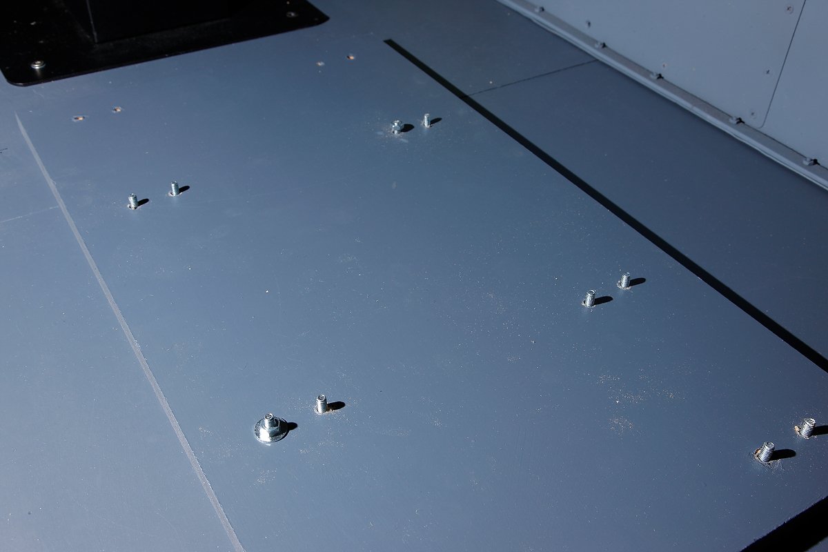
To minimise the chance of the seat moving when adjusted, I fabricated a mount that sits beneath each seat.  The mount, constructed from wood, is 16 mm in thickness and is bolted to the 16 mm thick platform floor (36 mm total thickness).  Rather than use wood screws to attach the seats, I decided to use 55 mm length bolts with washers; my thinking is that the bolts will provide far stronger attachment points, when installed through the seat mounts and platform floor, than wood screws. 

Attaching the Seats

The first task was to cut and paint the seat mounts which was straightforward. Each seat was then attached to its mounting base and then secured to the platform in the correct position with bolts. The biggest problem was actually lifting and moving each seat into position on the platform, each seat and segment of flooring weighs over 50 kg.

Correct Positioning

The correct positioning of the seat and seat mount is very important.  Boeing specification states that the distance from the front of the seat to the MIP is 340 mm, however, this depends on where you are measuring to and what type of MIP you are using.  The measurement if using a FDS MIP is from the front of the claw feet to the forward edge of the lower kickstand.  This measurement is 440 cm.

wooden platform mount connected to claw feet of weber seat. the seat and mount are them positioned correctly on the platform and secured using bolts

The seats move forward and aft, by pivoting over the secured claw feet (see video); therefore, if the measurement is out by a cm or so it is not really an issue as the seat movement can take up the difference. 

It Works….

With the platform floor secured to the base it was time to trial the seats.  Both seats work well and there is no movement or flexing at their attachment points.  There is also no movement where the seat mounts join the platform floor.

I think it was overboard using 16 bolts and bolting through 36 mm of woo!  But, I wanted to make sure the seats did not move on their base as I didn't particularly want to remove them and start over again. 

Next on the list is installing the ACE yoke and throttle quadrant.

The wooden platform has since been replaced with a modular aluminum structure.

Weber Seat Mechanics - They Are Built To Last

The under seat workings of the Weber seat: Heavy duty chassis, the smaller of two heavy duty springs, two of three cables and the cylindrical hydraulic/pneumatic cylinder

In a earlier journal post (Weber Captain & First Officer Pilot Seats), I discussed the purchase of two Weber pilot seats.  What I didn’t discuss was how these seats function.  Weber seats, although constructed from aircraft rated aluminium are not light in weight; each seat weighs approximately 40 kilograms.  Most of the weight is associated with the robustly constructed underside the seat.

The seat has four movements:

  • Forward and aft movement;

  • Vertical rise;

  • Recline of back rest; and,

  • Under leg rise & fall.

Mechanics

Each movement is initiated by moving one of three solid lever on the pedestal side of the seat.  The lever operates a push style button connected to the end of a cable.  As the lever is moved the button is pressed or released with a corresponding press and release from another button at the opposite end of the cable.  The compression needed to allow these movements is controlled is by a very heavily constructed tensile spring that is contained within a cylinder.  This in turn is connected to a hydraulic/pneumatic piston that allows for greater ease in movement.

The mechanics control the subtle movement of the rear seat recline (like in an automobile) and the under leg rise and fall of the portion of the seat, that can be raised under the calves to allow more or less reach to the rudder pedals.  When the desired position is reached and the lever released, a heavy duty ratchet / cog is engaged locking the position in place.

The two most aggressive movements of the seat are the forward and aft movement of the seat and the vertical rise. This and the non use of J rails are two reasons that Weber Seats are attached to the flightdeck floor by 16 attachment bolt points by eight claw feet (duck feet) for each seat.

Weber manufactures a number of different variants: hydraulic, electric, spring or a combination thereof – there are several variations in use throughout aircraft fleets. The seats I am using are spring and hydraulic controlled. 

Weber Captain & First Officer Pilot Seats

weber seats on trailer

A call from DHL Freight logistics alerted me to the fact that another large crate had arrived at the local airport for pick-up.  It was too early for the consignment to be the MIP, so the next contender was cockpit seats.

I wasn’t going to purchase pilot seats until the project was nearing its final phase.  However, genuine B737 seats are becoming more difficult to find in good condition, and when I was offered these seats, I decided to purchase them. 

Boeing aircraft use for the most part two types of aircraft seats: Ipeco and Weber; the former being the more modern seat design with adjustable J-rails.  Personally, I find the Ipeco seats to be rather uncomfortable and the configuring of J-rails can be painful.  Weber seats bolt directly to the floor, so as long as you have the correct measurements for the bolt down locations, there shouldn’t be any further problems.  Both the Ipeco and Weber seats have several seat levers to allow for correct and comfortable positioning.

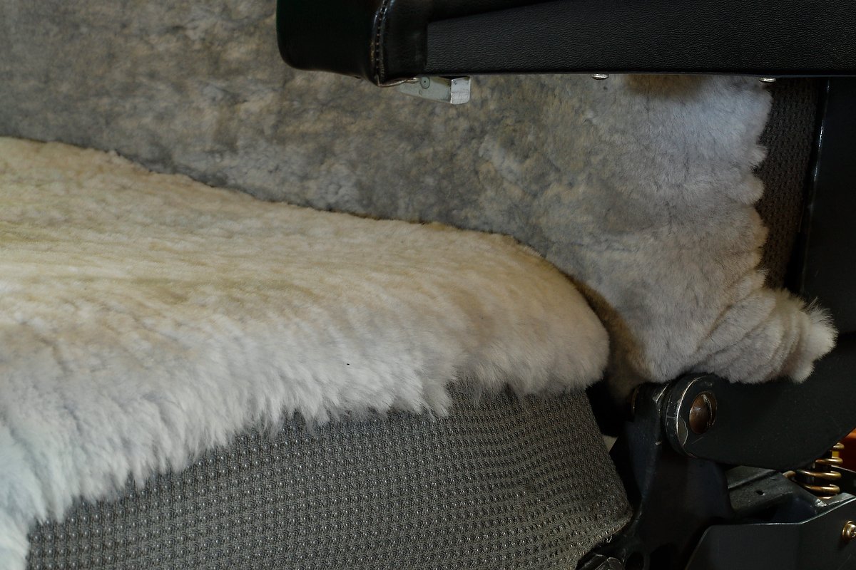
Weber seat cushions are either manufactured from cloth, which are the seats I have, or they have sheepskin covers sewn over and into the cloth.  At some stage in the future, I may have sheepskins installed over the seats, but at the moment this is a secondary issue.

Apart from some very minor cosmetic issues associated with the plastic molding on the rear of one seat, both seats are in excellent condition.  You have to remember that seats are always in used condition and probably have flown thousands of hours.  Before their new home in the simulator, they were fitted to a 737-500 series aircraft belonging to South West Airlines. 

Minor Overhaul of Flight Officer Seat

Although cosmetically the seats look OK, the right hand seat (flight officer) didn't seem to be operating correctly.  Inverting the seat, I was shocked to see a built up of dirt, grim and dust over the mechanism that controls the movement of seat.  Disassembling the components, I also discovered a broken split pin which was stopping the connecting cable, which controls the vertical rise in the seat, from working.  After cleaning and replacing the broken split pin, I lubricated all the areas requiring lubrication.  PRESTO, the seat now works as it should.

Leg Attachment Points - Four Seat Movements

Each seat has 16 attachment points to secure the seat to the floor.  One reason for this is that when you alter the position of a Weber seat, especially forward and aft, the pressures exerted on the seat legs are very high.  The seat has four movements: back reclining (like in a motor car), vertical rise (upwards lift of about a foot or so in height), under leg lifting and forward and aft seat control.  The last movement is needed as Weber seats do not use rails.

CASA Approved?

I was inspecting the seat feet (called duck feet because of their shape when my wife came into the room - she commented ’I hope their CASA approved’.  The first snipe - no doubt more will come  :)  I dare not try the seat harness.... (CASA is the Civil Aviation Safety Authority in Australia)

Oh and before you ask - yes the seats are very comfortable.

DZUS Fasteners

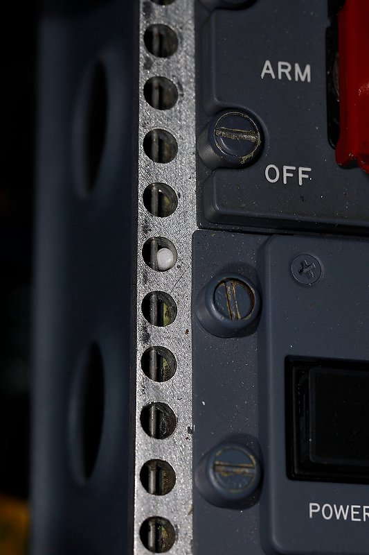
OEM DZUS FASTENERS AND RAIL

When I became interested in constructing a simulator, I heard knowledgeable people stating DZUS this or that - I had no idea what these individuals were referring to, let along how to pronounce the word.

Dzus (pronounced Zooss) is a proprietary name for a type of quarter-turn fastener often used to secure skin panels on aircraft.

It was invented and patented by a native Ukrainian William Dzus (Volodymyr Dzhus) in the early 1930s. Quarter-turn fasteners are used to secure panels in equipment, airplanes, motorcycles, and racing cars that must be removed often and/or quickly. These fasteners are notable in that they are of an over-center design, requiring positive sustained torque to unfasten. A DZUS fastener will correct itself rather than proceed to loosen as it would in threaded fasteners.

Real DZUS Fasteners

Finding individual real DZUS fasteners can be difficult as they are mostly attached to avionics panels, and the vendor wants to keep them with the panel. If you search long enough, eventually you will find an aviation scrap yard that has them available as separate units. I recently saw several selling on e-bay quite cheaply. I have a small collection of grey, black and bare metal coloured fasteners in varying condition, obtained from a scrapped Boeing 737 (I bought them in a 30 piece lot). The fasteners are needed to lock down any avionics panels to the DZUS rails of the OEM center pedestal and overheads and some panels in the MIP.

Reproduction DZUS Fasteners

If you’re using a OEM center pedestal with a DZUS rail, reproduction panels such as those produced by CP Flight or SISMO will not be able to secure to the rail easily. You will need to enlarge the circular hole along the edge of the module to allow the real DZUS fasteners to fit easily and correctly. If you decide to do this, be mindful that you don’t damage the edge of the module when you enlarge the circular hole. I used a titanium drill bit and carefully secured the panel in question in a vice on a workshop bench (wrapped carefully to avoid the vice jaws damaging the module) before drilling.

If you have replicated the center pedestal from MDF or wood and want to use something more realistic than boring screws to attach your panels, you can purchase after market'look alik’ DZUS screws. Basically these are wood screws with DZUS style heads on them. Good quality aluminium DZUS screws can be purchased from GLB Flight Products. I’ve used these on my earlier generic flight deck and they work very well and look just like the real ones…

Acronyms

OEM - Original Equipment Manufacturer.

Sticky Autothrottle Button - Repaired

oem autothrottle button. note the circular circlip

I noticed soon after the throttle quadrant arrived that the engine number one auto throttle button was a bit sticky.  Depressing the button, it would stay pressed in for a few seconds even though pressure had been released.  The autothrottle buttons are one-way buttons meaning that they are click buttons.  It’s probable that after many hours of service, sweat, dead skin cells and dirt has built up on the inner button behind the spring mechanism; a friend suggested that DNA analysis of the built up debris would probably provide a list of suspect pilots!

Whilst the button was still in place, I attempted to loosen the built up material using a can of pressurized electronic cleaner fluid.  The fluid, I hoped would dislodge any loose material before evaporating.  Unfortunately, this didn’t work in the long run, although once lubricated with the evaporate solvent, the button operated correctly for a short time.

oem autothrottle button removed

Circlip

The button is held in place within the throttle handle by a ½ inch circlip.  Beneath the circlip and button there is a spring mechanism that pushes the button out after being depressed.  Using a pair of circlip pliers, I very carefully removed the circlip making sure that the spring mechanism of the circlip didn’t propel my button out the window and into the garden! 

With the circlip removed, the inner portion of the throttle handle slides out revealing the button and attached wiring.  The button is a modular design (shaped to fit inside the throttle handle) and unfortunately cannot be disassembled further, Therefore, I reassembled the button and sprayed a small amount of silicone spray around the button, allowing the silicone solution to penetrate around the the edge of the button. 

The silicon lubricant (which is non conductive, so there is no issue with power shorting) seems to have solved the problem as the button no longer sticks, however, this is only an interim solution.  I'll search for a replacement button module.  Sometimes the most simple solution will fix your problem.

No doubt I can purchase a new replacement from Boeing for err $800.00....  I think not.  Eventually I'll find a disused button module in my travels.