Freight Dispatched - Throttle Quadrant Australia Bound

A300-600 FedEx. Flaps2approach freight was dispatched on this aircraft (Maarten Visser from Capelle aan den IJssel, Nederland, N725FD A300-600 Fedex (4542200103), CC BY-SA 2.0)

It’s taken considerable time with frequent delays since I sold my earlier B737-300 series throttle quadrant, in October 2012, to make way for a replacement 600 series TQ with three-bay pedestal.

LEFT: FedEx. Copyright Bob Wood, Airplane Pictures.Net

As I expected, “scope creep” reared its head and the original requirements changed considerably over time.  It’s almost like leaving the house to buy a second hand car and coming back with a brand new jeep with all the accessories.

Use a Freight Forwarder

Freighting something as heavy and as large as a TQ, from the United States to Australia is not without cost and I’m fortunate to be in good stead with a competent Australian freight forwarder. 

A freight forwarder's job is to look after the logistics of getting the freight from point A to point B as expeditiously as possible.  Forwarders also complete all the required paperwork that is requested by customs authorities in both the country of export and import.  A good forwarder will do everything, albeit at a cost to you; however, the fee they charge is often worth the expense, as completing the required paperwork can be very difficult and if not correctly done will result in delays and storage charges.

Often a freight forwarder will sub contract his equivalent in the country of export to look after the exporting aspects of the freight.  A forwarder has access to any number of airlines and attempts to secure a freight rate that is acceptable to the client. 

Freight rates behave like shares on the stock market, and prices fluctuate widely depending upon the price of fuel, whether the freight can be back-logged (added to a pre-paid shipment belonging to someone else) or is dispatched stand alone.

How the Freight Industry Works

The way it works is quite simple – the freighter will charge you based on the cubic surface area or weight ($$$ / kilogram) of the crate.  The amount you pay is whichever is greater!  To this there are other charges added such as: airport fees, security fees, customs clearance fees, tax, import duties, airline handling fees, terminal fees, cargo automation fees, export clearance charges and a truck tail-lift pick-up fee.  This is above the actual cost per kilogram to send the freight and any domestic carriage, pick-up and storage charges.

You're probably thinking that sea freight is less expensive and you are correct; however, shipping terminal fees usually negate much of the saving, not too mention a lengthy wait time and a higher cost for insurance.

Carrier & Route Change - QANTAS then FEDEX

The freight industry is not a squeaky clean industry and under-the-carpet arrangements are commonplace.  If another carrier has space that is being sold at a cheaper rate, then your freight often will be shipped with the airline with the lesser expensive freight charge.  Unfortunately, this saving is not passed along to the customer, but equates to a higher profit for the freighter.  

The freight business have a term they use called "time sensitive", which basically translates to "we do what we want and you wait"!

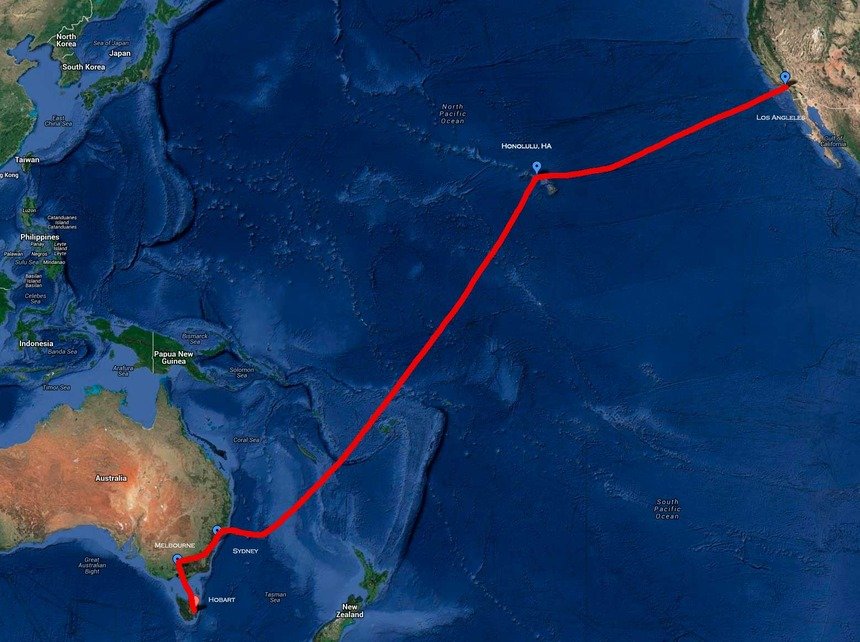
For example, my freight was supposed to be freighted with QANTAS for a quick Los Angeles – Melbourne (KLAX-YMML) flight followed by a domestic service further south to Hobart (YMHB). 

However, space became available with FedEx at a cheaper rate than offered by QANTAS and the Ameriican freight forwarder made a carrier and route change.  Instead of LosAngleles to Melbourne, the crate was dispatched via a FedEx MD11 from KLAX to Honolulu (PHNL).  From here it will travel via a Fed EX 747-400 through to Sydney (YSSY) and then onto Melbourne.  From Melbourne a domestic carrier will continue the pilgrimage to Hobart…

For the consigner (me), the longer a trip takes and the more times the freight has to be unloaded, stored and reloaded into another aircraft the higher the probability of potential damage.  If your wondering what could go wrong, think about how heavy freight is moved about - they use a fork lift!

At least FedEx, like DHL and UPS are specialists in moving freight.

Large Crate - Taking Advantage of Volume

I've spent considerable time over the last 10 months or so tracking down and purchasing genuine B737 OEM parts required for the simulator.  These have been stored at my friend's house and have been packed inside the crate along with the TQ.  The crate is full to the brim of "goodies" that will keep me busy for months... 

It's good to know I've saved considerable future postage costs and reduced the global carbon footprint by being able to add things to this shipment.

Impatient Wait

It’s an impatient wait, knowing that as I write the crate of “goodies” has landed in Sydney and has been transferred to Melbourne.  The next hop is to Hobart, Tasmania.  It's a fact of life that transporting anything to Hobart (an island state) takes a inordinate amount of time, so delivery is not expected to mid next week.

It's said that waiting builds character; "I seem to wait all the time....."

Oh and if your curious, the cost to send 110 kilograms chargeable weight from the US to Australia is $1453.00 AUD total.  Whoever said that building a simulator was cheap, should be "shot on the spot"!

I'm looking forward to getting back into construction mode and posting new progress updates, explanations and photographs.


Update

on 2013-08-15 22:23 by FLAPS 2 APPROACH

The crate has arrived....  It's much bigger than I anticipated.  This is the crate at the side entrance door to the house.. 

I had to make a winch and cradle system to enable me to get the crate, which weighs 110 kilos up and over the stairs and into the house.

At last, I now can get back into the construction phase of the simulator!

Time to find my wire, drill, clippers and multimeter.  There are so many OEM parts - which do I start on first.

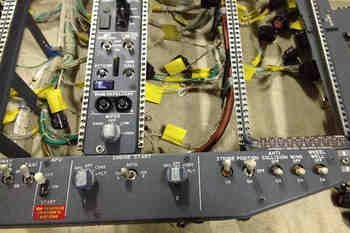
Genuine B737 Forward & Aft Overhead Panels Purchased

For some time I’ve been debating whether to use a reproduction or OEM forward and aft overhead panel.  I have been favouring an OEM panel as this is in line with using genuine parts in the simulator, however, the overhead is a complicated piece of kit and ensuring complete functionality would be a challenge.

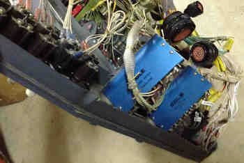
RIGHT:  Forward Overhead Panel.  The centre panels will be replaced to conform to a 737 Next Generation.  Panel was removed from a United Airlines 737-300 aircraft.

Certainly, using an overhead panel made by Flight Deck Solutions (FDS) is an easier option, however, despite their reproduction panels being high quality, there are discernible differences between reproduction and OEM panels.  

OEM 737 Overhead Panel Purchased

My decision was made for me when I was told a forward and aft overhead had become available from a recent 737 pull down.  Rather than remain indecisive, I thought I’d jump in “boots and all” and purchase it.  The two overhead panels have come from B737-300 and include the frames, DZUS rails, center panels, Cole engine starter switches, landing gear toggles and various other knobs and toggles.

I’m impressed at the condition of the panels; usually when panels are removed from an aircraft in a tear down yard there is little care given, and the frames become scratched, dented, or damaged in some way.  The frames I have purchased appear to be in relatively good condition.  

Cole Switches

I was fortunate that the two engine starter switches (Cole switches) were included.  These switches are made to exacting requirements and use a solenoid mechanism. 

LEFT:  Difficult to find operating Cole switches are used on all Boeing airframes from the 727 through to the Next Generation.

Purchasing Cole switches individually is quite expensive, so I'm pleased they were not striped from the overhead.

Panels and Backlighting

When I began to construct the simulator in mid 2011, I was adamant that backlighting should match that of the MIP, throttle quadrant and center pedestal.  I believe it was around 2006 that Boeing began to replace bulbs in favour of LEDS.  Certainly, the latest made Boeing uses LEDS. Therefore, my opinion has changed and I am happy to mix bulbs and LEDS (within reason)

The use of bulbs in the overhead uses a lot of power and generates considerable heat; using LEDS minimises power consumption and produces less heat.  If the LEDS are installed correctly, their resultant light is very similar to that of bulbs, and the brightness observed in the real aircraft.

Ultimately the back lighting will be dependent on whether I decide to use older style genuine Boeing panels or reproduction panels.

Realism & Authenticity - How Far Do You Go

Some flight deck builders go to extremes to ensure their flight decks replicate exactly what is seen in the real aircraf,t and while this is admirable, this is not the route I am 'religiously' going to travel.  There has to be compromise between replicating something exactly and having a functional flight simulator.

The end product will  be a combination of genuine (OEM) and reproduction parts - mostly OEM.

Furthermore, serious thought must also be given to how the overhead is going to be installed to the simulator; whether it be to a shell, such as produced by FDS or to a custom-made roll cage assembly.

I'll keep the Blog updated as parts are found and the overhead is developed.

  • Unfortunately I do not have any high quality pictures. These images were supplied by the vendor. Currently the overhead is still located in the US.  In time better quality images will be uploaded.

B737-800 Cabin Phone System Panel - Center Pedestal

oem 737-800 cabin phone panel: Panel has three push buttons with backlighting and legends, and one toggle button

I recently acquired an avionics panel that is a little different to the norm.  The panel was acquired from a company that was responsible for altering the on-board communication system for 50 Boeing 737-800 jetliners; the aircraft were being refitted with global communication equipment.  The upside for me was that the panels were being decommissioned and were not required by the supplier.

Late model 737 Next Generation panels are uncommon to find; therefore, it is interesting to observe the differences between the older style classic panels regularly seen on e-bay, and a newer style panel. 

The first thing that comes to mind, other than condition, is the lack of a rear box assembly on this panel.  Instead of an aluminum box, the wiring is protected by a stainless bracket assembly.  The wiring harness is also more refined and neater looking, while the backlighting, rather than using 5 Volt bulbs uses LED technology.

oem 737-800 cabin phone panel. note the crispness of the legend

LED Technology

Most people are familiar with the 5 volt incandescent bulbs used to illuminate the light panels in Boeing aircraft - the bulbs produce a soft yellow-orange hue.  The colour temperature is in stark contrast to the white hue produced by LED technology. 

I believe that airframes post 2006 utilise LED technology.  Notwithstanding this, until older airframes are phased out, panel lighting will be a mixture of incandescent and LED lighting, or a combination thereof. 

Matching Colour Hue

Attempting to match the backlighting colour hue, especially in the center pedestal and overhead panels has always been a challenge for flight deck builders, especially when using an assortment of older style OEM panels and panels made by differing companies (FDS, CP Flight, Open Cockpits, SimWorld, etc).  

Wiring is very neat and the panel does not utilise the more commonly found aluminum box structure

What many virtual pilots forget, is that the only purpose for an airlines’ existence is to generate income and a profit for the company. Pilots on the other hand are more concerned with flying the aircraft. 

There is very little thought as to whether a panel's backlighting is the same colour hue throughout all the panels.  If and when a panel needs to be replaced, a technician’s only concern is getting a workable and certified instrument fitted into the aircraft as quickly as possible. 

it is not unrealistic to have a few LED panels scattered amongst older bulb illuminated panels

Cabin Phone System Panel - What Works

Although there is no obvious use for this panel in the simulator, it is a good-looking panel that improves the overall aesthetics - it fills a 'gap' in the three-bay center pedestal.  The buttons do function and when depressed change colour and provide different cautionss.  Lifting the red cover and pushing the toggle to test causes the third button to illuminate 'smoke' in orange.

Although the panel has not been connected to an interface card, it is an easy process to connect a PoKeys or Leo Bodnar interface card to the Canon plug. ProSim737, nor Sim Avionics include functionality with this panel.

Replacement OEM 737-500 Throttle & Center Pedestal - Conversion to NG Style

737-300 throttle quadrant with old style paddle-style stab trim levers

The last few months have seen quite a bit of activity regarding the throttle quadrant and center pedestal, which has culminated in me selling my former 737-300 series throttle quadrant and pedestal and replacing it with an another unit from a late series 737-500 aircraft.

Brief Recap

In late 2012, I decided to convert the 737-300 throttle to full automation.  A dilemma I faced was whether to keep the throttle unit as a 300 series throttle with the attached two-bay pedestal, or do a full conversion to make it similar to the Next Generation. 

After careful consideration, it was decided convert the throttle quadrant.so it appeared as close as possible to the Next Generation.

Stab Trim Switches

One of the biggest differences, apart from thrust lever handles, between early model throttle units and the Next Generation units is the stab trim cut out switches.  On the earlier 300 series units, the switches are paddle / lever style switches while the Next Generation uses toggles and T-Locks.  T-Locks are a safety feature and sit beneath the toggle switches and are spring loaded; the pilot must push down the T-Lock to activate the toggle.  

To convert the trim switches requires cutting out the old switches and fitting new reproduction Next Generation switches.  This is a major task requiring precision work.  Although reproduction switches can be made, the reproduction T-Locks don't operate as the real T-Locks should.  I did search for some genuine T-Locks and toggles, however, my search was fruitless as these parts appear to be reused by airlines (or recycled).

Replacement 500 Series Throttle Quadrant & Three-Bay Center Pedestal

A friend of mine informed me that a late model 737-500 throttle quadrant was for sale.  This unit was in better shape than my existing throttle, included the genuine Next Generation style stab trim switches complete with T-Locks, and also had a three-bay center pedestal.  It appears provenance was shining on me as the new throttle appeared for sale a day before the stab trim switches were about to be removed (with a metal cutter...)

The throttle and center pedestal were purchased (you only live once!) and the 300 series throttle sold to an enthusiast in Sweden.

Next Generation Conversion

To bring an earlier style throttle and center pedestal to appear similar to a Next Generation throttle quadrant requires, at a minimum:

  • Attachment of a Next Generation style throttle lever shroud to existing aluminium levers;

  • Removal of TOGA buttons and relocation to bring design in-line with a Next Generation (the buttons are identical, but the housing is different);

  • Possible replacement of the stab trim switches;

  • Painting of throttle housing and center pedestal from Boeing grey to Boeing white; and,

  • Painting of all throttle knobs from Boeing grey to Boeing white.

The biggest hurdle is usually replacing the trim stab switches, however, as these are already present on the new throttle, and are the Next Generation, considerable time and expense was saved in not having to replace them.

Main Differences - Next Generation & Classic

The Boeing airframe that most people associate with today begins with the 737-200 and ends with the 737 Next Generation.  In between we have the classics which refer to the 737-300, 400 & 500 series airframes. The 737 Next Generation series includes the 737-600, 700, 800 & 900 series airframes.

The main differences between a classic and Next Generation throttle quadrant are:

  • The stab trim switches are slightly different; the classics having two flat levers while the Next Generation has toggle-style buttons with T-locks;

  • The throttle thrust lever handles; the classics are bare aluminium and the Next Generation is white aluminium that is ergonomically-shaped.  The TO/GA buttons are also positioned in a different place on the Next Generation.  The knobs (handles) on the levers are also coloured white rather than off-grey;

  • The method that the throttle thrust levers move during automation.  The classics move both thrust levers together when auto throttle is engaged.  The Next Generation moves each lever individually in what often is termed the throttle dance (this is due to the computerised fuel saving measures incorporated in the Next Generation);

  • The spacing (increments) between each flap lever position is identical in the Next Generation, but is different in the earlier series throttles;

  • The center pedestal in the classics is either a two-bay pedestal (early 300 series and before), but more likely a three-bay pedestal.  The Next Generation always has a three-bay pedestal.  Base materials for the center pedestal are also different - aluminium verses a plastic composite material;

  • The speedbrake knob is very slightly more elongated on the Next Generation unit; and,

  • The telephone, circuit breakers and mike assembly differ in type and location

Next Generation Skirt - Thrust Levers

Boeing when they designed the Next Generation style throttle didn’t design everything from new; they added to existing technology.  All Next Generation throttles utilise thrust levers which are identical to those of earlier units.  

Boeing designed a shroud or skirt that attaches over the existing thrust levers encapsulating the older thrust levers and sandwiching them between two Next Generation pieces.  The assembly is made from aluminium and is painted white.

The TO/GA buttons are located in a different position on the Next Generation units, although the buttons used are identical.

To alter the position of the TO/GA buttons you must detach  the small aluminium box from the 300 series thrust levers, remove the TO/GA buttons, and then re-solder the buttons in the appropriate location on the new unit.

I did not make the Next Generation skirt for the thrust levers, but rather had fabricated, from design specifications, a reproduction skirt.  The skirt is produced from aluminium and replicates the dimensions of the Boeing part.

Time-line, Functionality and Conversion

The throttle is initially being converted in the United States.  The advanced work (automation) will be done by a good friend in California, and then I will follow on with more mundane tasks.

The replacement unit will feature several improvements which will allow: full motorized functionality, full speed brake capability, accurate trim tab movement, alternate trim wheel spin speeds, correct park brake release, trim wheel braking and several other features. 

I want the functionality of the throttle to be as close as possible to that found in the real aircraft; therefore, the methods used to ensure this functionality will be slightly different from the norm.

When the throttle is fully functional and tested, I'll publish a post providing further information and detailed photographs of the various functions.

It is hoped everything will be completed, and the throttle and pedestal installed by late May 2013.  The next month or so will be quite exciting.

Two-bay Pedestal Will Be Missed

I know I will miss the narrower two-bay center pedestal.  A major advantage that will be lost is the ease in climbing into and out of the flight deck; the two-bay provided more room between the pedestal and the seats.  At some stage, I probably will need to install J-Rails because the seats I'm using are fixed-claw feet Weber pilot seats; J-Rails will be needed to allow lateral seat movement.

BELOW:  Montage of several images showing main visual differences between 737-300 classic series throttle quadrants and the 737 Next Generation. The 737-300 throttle is my old throttle but, the Next Generation throttle quadrant belongs to a mate of mine.

Montage of several images showing main visual differences between 737-300 classic series throttles and the 737 NG style throttle units. The 300 series TQ is my old throttle unit but, the NG Throttle quadrant belongs to a mate of mine

Reference Nav Data - CDU Functionality Explained

In past posts, I’ve documented some of the functionality of the Flight Management Computer (FMC) as displayed by the Central Control Unit (CDU).  Following on with this theme, let’s look at four navigation data functions the FMC is capable of: Reference Nav Data, Nav Options, Nav Status and Nav Frequency Changes.

Before continuing, the FMC/CDU is controlled by the avionics suite you are using; whether it is ProSim737, Sim Avionics or whatever.  Each avionics suite provides differing functionality; therefore, if something does not operate as indicated, it maybe a limiting factor of the avionics suite in use.

Note:  This post follows standard terminology.  lsk3R means line select key 3 right.

------------------------------

A:  REFERENCE NAV DATA

Occasionally, you will need to cross check information and the frequency of a specific navaid.  

The Reference Nav Data display is part of the Nav Data page and can be assessed by the INDEX page:

INIT REF / INDEX / NAV DATA (lsk1R)

The screen will show three available options: Enter WPT Ident, Navaid Ident and Airport Ident.

Example:  Type HB into the navaid Ident.  Two pages will be displayed showing all the HB Idents from the navigation database.  Selection of the appropriate navaid (HB) will present a further page displaying the following information:  Navaid WPT, Airport and Ident code, Latitude, Longitude, Frequency, Elevation and magnetic variance.

NOTE:  If you cannot identify the ident by name use the Longitude and Latitude coordinates.

------------------------------

B:  NAV OPTIONS & NAV STATUS

Following on from the Reference Nav Data page are:  Nav Options and Nav Status.

Nav Options and Nav Status can be assessed two ways:

1:  INIT REF/ INDEX / NAVDATA (lsk1R) / NAV OPTIONS (lsl6R)  

2:  PROG (progress) / NAV STATUS (lsk6R)  (use when in flight)

Two consecutive pages are available: Nav Options and Nav Status.  By default, Nav Status (page 2/2) is displayed.  Use the PREV and NEXT PAGE keys to cycle between the two pages.

Nav Status - page 1/2

This page provides you with a list of the closest navaids including frequencies.  It also indicates the currently set identifier and frequency for NAV 1 and NAV 2 (as set on the NAV 1/2 radio).

Nav Options - page 2/2

This page can be used to inhibit a particular waypoint or station.  By inhibiting a navaid, it will not be able to be used by the CDU to calculate a navigation solution.  By default all navaid types are activated.  At crew discretion, two VOR and two DME stations can be inhibited.  When you inhibit a navaid it will be removed from page 1/2 and not be visible in the Nav Status page list.  The inhibited navaid will be reset when you reset the CDU.  

------------------------------

C: FREQUENCY CHANGE - ALTERING THE THE CDU

In usual practice, crew will alter the navigation, communication, ADF and transponder frequency on the actual panel located in the central pedestal.  However, often you may need to cross check frequencies, dial in a third frequency for positional awareness, or use a frequency from an avionics module not present in the pedestal or that is malfunctioning.

The alter Nav Data screen can be assessed by:

MENU / MAINT (lsk6R) / COM/NAV (lsk3L)

This will display a page showing all idents and frequencies currently being used.

COM 1, COM 2, NAV 1, NAV 2, ADF 1, ADF 2 AND EXPR

To alter a frequency, type into the scratch pad the frequency of the navaid and upload to the appropriate line.  To upload, select and press the key to the left or right of the nominated radio.  Changing a frequency in the CDU will also cause a corresponding change in the frequency of the selected radio (in the center pedestal).

Flow Route

When you work through the above four functions of the CDU, you will note that the INDEX function is always available.  This allows you to easily develop a flow route as you move between the various pages.  Once you know how the flow route operates, you will discover that the CDU is very much like a book with several hundred pages of information that is easily accessible via a few select menu keys.

As with all my posts, if you discover a discrepancy please contact me so it can be rectified.

BELOW:  Montage of images from the CDU showing various pages displayed within the Reference Nav Data.  CDU is manufactured by Flight Deck Solutions (FDS).  Click image to see larger.

Montage of images from the CDU showing various pages displayed within the Reference Nav Data.  CDU is manufactured by Flight Deck Solutions (FDS)

B737 Auto Brakes - Converting & Using a Genuine Auto Brake

oem 737-500 auto brake rotary and squib

Enthusiasts don’t normally give a second thought to the rotary type auto brake mechanism on the Main Instrument Panel (MIP); it works and that’s all that matters.  However, several reproduction rotarys do not entirely replicate the correct operation of the auto brake in the Boeing 737 aircraft.

In the real aircraft, a pilot has the ability to select between auto brake OFF, 1, 2, 3, and MAX.  The first three brake indications and off are achieved by turning the knob in a clockwise or anticlockwise direction, however, the knob stops at MAX.  To engage MAX, the pilot must pull the knob out from a retainer and then move it a further click to the right. 

The reason for this is quite simple; engaging auto brake MAX results in severe deceleration which can be stressful and uncomfortable for passengers, as well as creating undue wear and tear on the braking mechanism of the aircraft.  The function of pulling the knob is not replicated in reproduction auto brake switches.

Aviation Scrap Yard to Me

To my knowledge, the auto brakes operate and use the identical rotary mechanism throughout the Boeing aircraft series, the exception being the size and style of the actual knob mounted on the rotary.  The early model auto brake assemblies have a slightly larger knob, while those used in the 737-500 have a smaller knob that is identical to that used in the Next Generation aircraft (with the exception of the parallel black strips which is distinctly Next Generation) 

rear of own autobrake squib

Larger and Robust

If you have inspected any genuine aviation part, you will have noted that the size of the item is usually quite large in contrast to reproduction simulator part.  This is because a real part must be manufactured to take into account the nuances of pressure, fatigue, vibration, water and dust proofing, and be made as sturdy as possible to ensure operational longevity.  Genuine parts regularly are designed to military specifications and can withstand considerable abuse.   

Canon Plugs

The wiring used with an OEM part can appear complex with several wiring harnesses and a multitude of connections.  In a real aircraft, these wires connect to circuit breakers and a magnitude of interconnecting electrical components and power sources. All Boeing 737 aircraft use Canon plugs. Canon plugs make removing a panel straightforward for a technician and also provide a fail safe mechanism to ensure that specific wires are connected to their correct mate. Each Canon plug is different and can contain up to 32 differently arranged pin-outs. It is almost impossible to miss-mate two Canon plugs.  

With so many variables, it can be frustrating slow process determining which is the correct pin-out to use. 

Autobrake Mechanism -  Simpler than Most Conversions

The auto brake assembly is a lot simpler to convert than a more sophisticated avionics panel. 

If you already have an auto brake rotary and installed to your MIP, all you are doing is replacing the reproduction plastic rotary with a real OEM rotary.  The wires then connect to your interface card.  The only tricky part is determining which connection outlet on the real rotary to connect the wires to.  Determining this is either by trial and error or finding a schematic diagram for the rotary.  I was fortunate that I had access to the later…

using a dremel bit to carefully enlarge the hole in the panel so that the rotary shaft will fit correctly

Conversion and Retrofit

Remove from the MIP the reproduction auto brake rotary and front light plate.  Check to determine if the shaft of the genuine rotary will fit through the panel and MIP wall; the circumference of the hole may need to be widened.   If this is necessary, it’s important that you do not damage any IBL back lighting that maybe used in the light plate.  IBL is usually sandwiched between the back and front of the panel.

I used a dremel tool to gently and very carefully remove part of the light plate to allow the rotary to fit through the hole in the plate.  Do NOT use a drill as this may fracture the light plate.  

Fitting the Rotary Nut - Enlarging the Plate Recess

The rotary is securely connected to the MIP via a hexagonal-shaped nut.  Depending on your MIP manufacture, you may need to enlarge the hole on the rear of the plate to enable this hex nut to be recessed in the plate.  If you are using a MIP made by Flight Deck Solutions you will not need to do this as FDS have designed their MIP to fit genuine parts.  Use the dremel to gently enlarge the recess on the rear of the plate.  Be VERY careful not to damage the light plate; use the dremel tool very lightly.  

owm 737-500 auto brake squib showing multiple connectors and pin out codes

Wiring

The genuine rotary appears to look like a squid (the sea animal) with an assortment of wires emanating from screw connectors.

Remove all the wires and screws and thoroughly clean the unit with a suitable cleaner.  Do not discard the wires and connectors as you can probably reuse the high grade aviation wire; remember recycling is good and helps the environment.  You will note that each connector is marked by a printed number.  

The numbered keys for the autobrake squib keys and function are outlined below:

  • 31 - common or earth

  • 32 - RTO

  • 33 - OFF

  • 34 - autobrake 1             1

  • 35 - autobrake 2

  • 36 - autobrake 3

  • 37 - autobrake MAX

Replace the screws in the appropriate connectors you will need to use.  Then add a section of wire (use the old wire first) to the connectors.  If you cannot reuse the sturdy clips, then use automobile electrical tabs.

If you have not done so already, before you cut the wires from the (to be replaced) “plastic” rotary, mark with tape and pen which wires connect to what function – RTO, OFF, 1, 2, 3 & MAX.  This will make it an easier task when reconnecting or soldering the wires.

Aligning Rotary on MIP

Aligning the autobrake rotary is important if you want the selector knob to align correctly with the engravings on the MIP.  If you look carefully at a reproduction rotary you will notice a circular lug that often is mated with a hole in the receiving metal - this stops the rotary from spinning on its own axis.  OEM parts do not have such a lug.  Rather, they have a circular washer that has a lug attached to it.  This washer slides over the shaft of the rotary along a defined groove.  The lug on the washer then meets with an appropriately positioned hole in the MIP to stop the rotary from swivelling.

Interface Card

If you are replacing a reproduction unit with an OEM unit, then an interface card is not necessary - connect the wires from the new rotary to those cut from the removed from the plastic reproduction rotary either by solder or using a terminal block.

However, if this is a new installation a Phidget 0/16/16 interface card will be required to assign the appropriate locations of the knob to their respective functions.

Is There a Difference?

Can I notice and feel the difference between the older reproduction rotary and the genuine rotary?  In a nutshell - a resounding yes. 

The genuine rotary is firmer to turn, engages with a distinctive audible click, and feels more robust.  The knob also feels different to the reproduction knob; probably because the reproduction knob is made totally from acrylic and a genuine knob, although made from similar material, has a stainless shroud around the inside of the knob.  This causes the knob to feel more secure on the rotary.

Annunciators

The autobrake has two annunciators - the Anti Skid INOP and the Autobrake Disarm korrys.   The simulator uses OEM annunciators and although these korrys have been wired separately, their connection with the autobrake is done through the avionics software in use.

Below is a short video showing the use of the auto brake assembly.  Ignore the speed reference knobs and fuel reset switch that need to be replaced with OEM knobs.


Auto Brake Usage

The auto brake is designed as a deceleration aid to slow an aircraft on landing or in rejected take off.  The rotary switch has four settings: RTO (rejected take off), 1, 2, 3 and MAX (maximum).  The brake can be disengaged by turning it to OFF, by activating the toe brakes, or by advancing the throttles; which deactivation method used depends upon the circumstances and pilot discretion.  

RTO and MAX provide similar braking power (3000 PSI).  1, 2, 3 and MAX provide an indication to the severity of braking that will be applied when the aircraft lands.   Often, but not always the airline will have a policy to what level of braking can or cannot be used; this is to either minimize aircraft wear and tear or to facilitate passenger comfort.  

In general, setting 1 and 2 are the norm with 3 being used for wet runways or very short runways.  MAX is very rarely used and when activated the braking potential is similar to that of a rejected take off; passenger comfort is jeopardized and it’s common for passenger items sitting on the cabin floor to move forward during a MAX braking operation.  This 'safety feature' is the reason why Boeing airframes have been designed so that the pilot must pull the auto brake knob before selecting MAX.

If a runway is very long and environmental conditions good, then a pilot may decide to not use auto brakes favoring manual braking.

The pressure in PSI applied to the auto brake and the applicable deceleration is a follows:

  • Auto brake setting 1 - 1250 PSI / 4 ft per second.

  • Auto brake setting 2 - 1500 PSI / 5 ft per second.

  • Auto brake setting 3 - 2000 PSI / 7.2 ft per second.

  • Auto brake setting MAX and RTO - 3000 PSI / 14 ft per second (above 80 knots) and 12 ft per second (below 80 knots).

To activate the auto brake it must be armed by selecting the appropriate setting using the auto brake selector knob (1, 2, 3 or MAX).  Furthermore, for the auto brake to engage the throttle thrust levers MUST BE in the idle position at touchdown.  If the auto brake has not been selected before landing, it can still be engaged providing the aircraft is travelling no slower than 60 knots.

The auto brakes can be disengaged by either pilot by applying manual braking or selection the auto brake selector knob to OFF.  Either action will cause the auto brake disarm annunciator to illuminate for 2 seconds before extinguishing.

Important Facet

It’s important to grasp that the 737 NG does not use the maximum braking power for a particular setting (maximum pressure), but rather the maximum programmed deceleration rate (predetermined deceleration rate).  You can only obtain maximum braking pressure using either RTO or when depressing the brake pedals.  Therefore, each setting (other than RTO) will produce a predetermined deceleration rate, independent of aircraft weight, runway length, type, slope and environmental conditions.

Auto Brake Disarm Annunciator

The auto brake disarm annunciator is coloured amber and illuminates when the following conditions are met:

  • Self test when RTO is selected on the ground.

  • A malfunction of the system (annunciator stays illuminated - takeoff prohibited)

  • Disarming the system by manual braking during an RTO or landing

  • Disarming the system by moving the speed brake lever from the UP position to the DOWN detente position.

  • If a landing is made with the selector knob set to RTO (not cycled through off).  If this occurs the auto brakes are not armed and will not engage.  The annunciator will remain illuminated

The annunciator will extinguish in the following conditions;

  • Auto brake logic is satisfied and auto brakes are in armed mode.

  • If the thrust levers are advanced during an RTO or landing ( 3 seciond delay is allowed after the aircraft has landed).

Personal Preference and Anti-skid

My preference for using auto brakes is, that when conditions are not ideal (shorter and wet runways, crosswinds) - I devote my attention to the use of rudder (for directional control) without concern for braking... the machine does the braking, and I take care of keeping the aircraft on the center-line...

Anti-skid automatically activates during all auto braking operations and is designed to give maximum efficiency to the brakes, preventing brakes from stopping the rotation of the wheel, thereby insuring maximum braking efficiency.

To read more on this subject navigate to: Rejected Takeoff (RTO) - Review and Procedures.

BELOW:  Photo montage of auto brake assembly.  Final conversion lower right picture - ready to install to MIP.

Photo montage of oem 737-500 auto brake.  Final conversion lower right picture - ready to install to MIP

B737 Blanking Plates - Cover That Unsightly Gap

OEM blanking plates complete with DZUS fasteners recently removed from a scrapped 737 - the dirt and dust is still on them!  Note three differing sizes - 1" 2" and 4"

No matter what style of simulator you are using or have constructed, you will most likely have a center pedestal installed.  The pedestal will be either a two-bay or three-bay type and be a genuine aviation part incorporating DZUS fastener rails, or a reproduction unit manufactured from wood, metal or plastic.

The two-bay pedestals, once allotted the standard Boeing avionics suite, usually have no  space remaining for additional avionics; however, the three-bay pedestals have substantially more 'real estate' and often gaps are remaining that are not filled with avionics.  Most enthusiasts either leave this space open which looks very unsightly, or manufacture their own plate to cover the gap.

OEM Blanking Plates

Why not use the real part….  

Boeing produces several blanking plates in varying sizes to be used to cover any 'gaps' not used in the center pedestal, forward and aft overhead panel, or Main Instrument Panel (MIP).  These plates are machine-grade light weight steel (or aluminum), are painted Boeing grey, and incorporate the required number of DZUS fasteners for attachment to DZUS rails.  The plates come in a variety of sizes with 1 inch, 2 inch, and 4 inch being the norm.

These plates are inexpensive and usually retail between $5.00 - $20.00 USD, and not only fulfill the task of covering an unsightly gap, but are easy to install, come pre-cut, are painted the right colour, and usually have DZUS fasteners attached to them. 

If not using real DZUS rails and your pedestal in made from wood or plastic, then it’s relatively easy to remove the fasteners and replace them with reproduction screw-type DZUS available from GLB Products.

Most aircraft wrecking yards carry these plates, as airlines regularly purchase them.  Failing this E-Bay often has blanking plates for sale. 

737 Classic Flight Deck - Scrap to Home Flight Deck

oem 737 cl scraped flightdeck ©

I thought I'd post an image of how a flight deck appears after removal from the aircraft. This is a flight deck belonging to a Boeing 737 classic series which is the model previous to the 737 Next Generation.  Anything of value is slowly being removed for either scrap metal, repair and reuse, or for possible inclusion in a home flight deck. 

One aspect of flight deck building I enjoy is finding and using recycled parts.  Who said recycling cannot be enjoyable  :)

I've made this image full size, so if you want to see it in more detail click the image (image use courtesy of Tim ©).

OEM Boeing 737 Control Columns - A Closer Look

OEM Captain-side 737-500 series control column.  Previously used by Croatian Airlines

The two control columns have been refurbished and installed into the simulator.  The control columns previously were used in a 737-500 airframe operated by Croatian Airlines. 

I was fortunate to have been able to secure these columns, and although there is some wear on the yokes, the buttons, electric trim switches, chart holders, and trip indicators are operational and in good condition.  Furthermore, a working stick shaker is attached to the captain-side control column.

In this article, I use the words control columns and yoke interchangeably.

Mechanical Set Up

To allow the two columns to be fitted to the 5 inch high platform, the lower cogs have been removed and replaced with bearings.  The bearings support a high strength stainless shaft that connects to a rotating disc beneath each of the columns; movement is synchronised between control columns.

Physical movement of the control column is registered by high-end string potentiometers and any movement converted to an electrical signal that can be read by the interface card.  The interface card used is a Leo Bodnar 836X joystick controller.

The interface card, electrical wiring and potentiometers are installed on a piece of plastic board mounted to a dust proof box and attached to the underside of the platform.  Access to the box is via the front of the platform.

Push and Pull Pressures

In the real Boeing 737 aircraft the control columns are hydraulically driven, and a fail-safe cable mechanism provides redundancy should the hydraulics fail.  The 737 is rather unique in that, although hydraulics control movement of the control column, the pressures needed to move the columns (by hand) are quite stiff.  Therefore, hand flying a 737 can be quite tiring; you must use a little muscle to move and maintain the position of the controls.

The specifications for the real aircraft state that the control column has a 37 pounds push/pull value +- 4 pounds, while the roll pressures are 12 pounds +- 3 pounds.  These pressures can differ from aircraft to aircraft, but fall within the published specifications. To replicate the push, pull and roll forces as accurately as possible, four heavy duty springs have been fitted to the column mechanism. 

Heavy duty pre-tensioned springs provide accurate static control loading

The control column pressure can be adjusted by either replacing the springs with higher or lesser tension springs, or by disengaging the outer springs. 

A pressure test determined that push/pull pressure is 20 pounds and roll pressure 15 pounds.  The push/pull pressure is on the low side, however, will be left as is for the time being.  Springs have been used rather than hydraulic rams due to the simplicity of a spring and ease of replacement.

Although the use of springs is rudimentary, it's acts as an interim measure until control force feedback is installed.  When this is done, the force required to move the control column will alter based on aircraft's speed, flap setting, landing gear position and other environmental variables.

The video at the bottom of this article demonstrates the linkage mechanism and springs in motion.

Configuration - Movement and Buttons

Configuration of the control columns is straightforward. Although there are two control columns, each column is linked to the other.  Therefore, only one interface card is required.  The buttons on the yoke, and the electric trim switch are connected to the outputs on the interface card.

Initial registration of the movement of the yoke and buttons is established in the Windows joystick calibration software.  Further calibration is either done directly in the flight simulation program, FSUIPC, or in ProSim737.  Although it is possible to assign buttons directly via the flight simulator set-up menu, the preferred method is to use FSUIPC or ProSim737.

Backlighting (Trip Indicators)

The actual yoke doesn't have backlighting; any illumination of the yoke is achieved by focusing the map light which is attached to the overhead panel.  However, the numbers on the trip indicators do have backlighting (to illuminate the numbers). 

Trip indicators are an airline specific option and do not come as standard issue.  Pilots use the trip indicator to 'scribe' the flight number of the flight, or to document the Vref speed.  Some crews never use the indicators.  I use the trip indicator as a ready memory pad to document the landing Vref speed (Vref+5).  The backlighting for trip the indicators is powered by 5 Volts.

oem chart holder and cheat sheet

Chart Holders

The chart holder is used to secure the approach plate (paper chart) in an area that it can easily be read during flight operations.  The chart holders have a folding mechanism beneath the plate that allows the holder to be either pushed flush to the yoke, or positioned at a user-selected angle. 

Another function of the chart holder is to provide a ready memory jogger for specific flight modes (checklist).  The adhesive transfer on which this information is printed is specific to each aircraft type and /or airline.  illumination of the chart plate, like the yoke, is achieved using the map light.

OEM Verses Reproduction

Several companies manufacture reproduction control columns: Precision Flight Controls (PFC), CH Products, Revolution-Sim and Ace Engineering to name a few.  Over the years I have used products from ACE, CH Products and PFC.  Without transgressing into a 'tit for tat' argument, you get what you pay for.  

A CH yoke retailing at $100.00 cannot be compared with an ACE yoke retailing around $1300.00, however, both products have been manufactured to cater towards differing segments of the market.  This said, the difference between ACE and PFC is marginal.  I cannot comment on Revolution-Sim having not used their products. 

So what is the different between a high-end reproduction yoke and a OEM yoke and column?

The main difference is the feel and finesse of the genuine item.  Boeing has spent a lot of money (more than PFC, ACE or Revolution-Sim combined) in the development and engineering of the control column, and this is very difficult to replicate in a reproduction.

The OEM yoke and column is engineered to provide faithful service for many years.  It's also built to suffer use and abuse from real-world pilots, and I am certain anything a virtual pilot can throw at it, will not cause any damage.  The buttons and electric trim switches are solid, feel good to manipulate and are very reliable.

Yoke Performance

The yoke moves left and right across its range of motion with a smooth and silky feel without staggering, binding or rough patches.  Likewise, the columns move forward and aft very smoothly.

The electric trim switches are far more responsive than the reproduction switches I have used.  A slight application of pressure to the switch engages the electric trim.  The electric trim switches response is a akin to a hair trigger on a firearm - it only needs a light touch to engage. 

The control column is very responsive, and if calibration has been done correctly, very accurate.  If the yoke is turned 15 degrees to the left, the measurement on the aileron tape is exactly 15 degrees.

Synchronization

I was concerned that synchronisation between the two control columns would not be perfect, however, my concern was short-lived.  The use of high-end bearings at the end of the control linkages removes any chance of slop (loose movement) between the two control columns. 

Yoke Switches

  • OEM 737 yokes have several switches and buttons.

  • Momentary press push button - auto pilot deselect.

  • Momentary rocker switch - electric trim up/down. This switch is interesting as it incorporates redundancy.

  • Momentary rocker - push to open channel (push to talk PTT).

  • Rocker switch - Intercom.

  • Trip Indicator - used as memory aid for flight number.

oem 737 flight controls in simulator

Appearance of Yoke - Used Look

If you carefully study the pictures of the yokes, you will observe that the yokes are not pristine condition, but show solid use (and probably abuse when it was striped from the aircraft).

The baked-plastic covering of the yoke shows scratches and some of the metal has been rubbed clean of paint.  Some enthusiasts dislike this look and prefer a brand new 'out of the showroom' appearance.  If this is you, then I suggest an OEM yoke may not be for you, unless you wish to completely overhaul the yoke and pay the large amount of money required to re-bake the plastic coating.

I like the 'used' look and feel it adds to the simulator.  I have been in many cockpits, and very rarely do you find a flightdeck in brand new condition, other than in the first few months of service.  More often than not, gauges, yokes and panels are scratched, dented and stained from many hours of sustained use from individuals that are more interested in flying, and going home after the flight, than maintaining the desk!

Below is a short video showing the under floor mechanism, springs and linkage rods.  If you listen carefully you will hear the springs creaking.  This is not an issue when the simulator is running as any noise is cancelled out by the noise of the engines and flight deck ambient noise (electrics, 400 hertz noise and wind).


Glossary

Control Wheel - Yoke.

FSUIPC - Flight Simulator Universal Inter-Process Communication (interface software that provides a bridge between flight simulator and outside programs).

OEM - Original Equipment Manufacturer (aka real aircraft part).

  • Updated 20 June 2020.

Digital Chronograph Running ProSim737 Software

The Main Instrument Panel (MIP), unless a special order is made, usually will not include a chronograph.  Depending upon the MIP manufacturer, the MIP may have a cut out for the chronograph, a facsimile of a chronograph or just a bezel. 

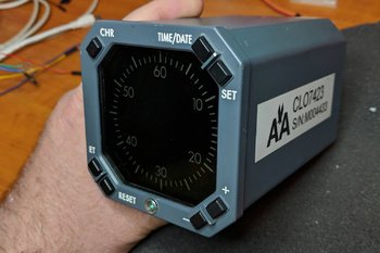
LEFT:   OEM chronograph used by America Airlines.  Although nothing beats an OEM item, in this case conversion is difficult; therefore; a reproduction chronograph was more cost effective.  Image courtesy of Micks737.

The Next Generation aircraft mostly use digital chronographs. The classic series airframes usually use (unless retrofitted) mechanical chronographs.

After Market Chronograph

There are several after-market chronographs that can be purchased.  SISMO Solicones produce a mechanical type that replicates the real world counterpart quite well, despite the awful orange-coloured backlighting.  Flight Illusion produces a quality instrument as does Flight Deck Solutions (FDS).  FDS replicate the digital chronograph. 

Chronographs are manufactured by several companies and not every chronograph looks identical, although their functionality is.  There are a few different styles available to an airline.  The main difference is in the number and shape of the buttons; round or rectangular.

No matter which type you decide, be prepared to shell out 250 plus Euro per chronograph; for an item rarely used it's quite a financial outlay.

Converting OEM Chronograph

Converting an OEM B737 mechanical chronometer is a valid option and the process of conversion is relatively straightforward.   However, finding a mechanical chronograph in operational order is difficult, as airlines frequently keep chronographs in service for as long as possible.  Converting a digital chronograph is also an option, however, the initial price of the item and then conversion make this an expensive exercise.  Add to this the fact that converting the chronograph, due to its internal digital electronics is very difficult (even if you use ARINC 429 protocol).

Another option is to use the virtual chronometer (Sim Avionics and ProSim737) and fabricate a reproduction bezel that overlays a small LCD screen.

ProSim737 Virtual Chronograph

Screen capture of ProSim737 chronograph.  ProSim737 have a Chronograph that can be used for the Captain and First Officer side of the MIP.  There are seevral version of the display that can be used

ProSim737 as part of their avionics suite have available a virtual chronometer.

The display used by ProSim737 is very crisp, the size is accurate (1:1 ratio), and the software allows complete functionality of the chronograph. 

To use the virtual version a small computer screen is needed on which is displayed the virtual chronograph.

Chronograph

A friend of mine indicated that he wanted to make a chronograph for the simulator and use the virtual ProSim737 display.  He also wanted to incorporate the four setting buttons and have them fully functional. 

The components needed to complete the project are:

  • A small TFT LCD screen (purchased from e-bay);

  • A standard Pokey interface card;

  • Several LEDS; and,

  • Four small tactile switches and electrical wire. 

I currently use an Main Instrument Panel (MIP) fabricated by Flight deck Solutions (FDS).  Therefore, the chronograph bezel used in this project was that supplied by FDS.

The screen used was 5.0" TFT LCD Module with a Dual AV / VGA Board 800x480 with a 40 Pin LED Backlight. 

The screen was small enough that it just covered the circular hole of the cut out in the FDS MIP.  The TFT LCD screen uses a standard VGA connector cable, 12 Volt power supply and a USB cable to connect the POKEY card to the computer.  

The holes in the box provide ventilation for the Pokeys card.  The only portion of the box that is visible from the front of the MIP is the bezel and four buttons

Two-part Fabrication

FDS supply with their MIP a bezel with four solid plastic but non-functional buttons.  The bezel does not support direct backlighting, nor does it have enough space for tactile switches or wiring. 

Therefore, the FDS bezel must be modified to accommodate the wiring for the switches and LED illuminated backlighting. The easiest way to approach this modification is to use a Dremel rotary tool with a 9902 Tungsten Carbide Cutter.

Place the bezel on a hard surface using a towel to avoid scratching and damaging the bezel.  Then, with 'surgical' accuracy and steady hands carve out several channels (groves) at the rear of the bezel.  The channels enable placement of the miniature tactile switches, small LEDS and wiring. 

Space is at a premium, and to gain addition real estate, the LEDS were shaved to remove excess material.  This enabled the LEDS to fit into the excavated groove on the bezel.  Be very careful when using the carbide cutter to not punch out onto the other side of the bezel. 

The four solid plastic front buttons on the bezel are carefully removed and small tactile switches attached (glued) to the rear of each of the buttons.   26/28 AWG wire is used to connect the tactile switches (using common ground leads) to a PoKeys interface card. 

The box is not seen as it's attached to the rear of the MIP.  My friend's humour - several warning signs suggesting that I not tamper with his creation :)

Box Fabrication

A small box needs to be fabricated to house the Pokey card.  The size of the box is controlled by the size of interface card used and the length and width of the LCD screen. 

A box is not required, however, it's a good idea as it illuminates the need to seal the LCD screen to illuminate dust ingress between the screen and overlying glass in the bezel. 

The material used to fabricate the box is plastic signage card (corflute); real estate agencies often use this type of sign.  The main advantage of this material is that it’s not difficult to find, is light in weight, and it's easy to cut, bend, and glue together with a glue gun.    

After the Pokey card is installed to the inside of the box, and the LCD screen attached to the front edge, the bezel needs to be secured to the front of the LCD screen.  The best method to attach the screen and bezel is to use either glue or tape. 

A hole will need to be made in the rear of the box to enable the fitment of the USB and VGA connectors.    Small holes punched into the side of the container ensure the LCD screen and PoKeys card do not overheat.  If you're concerned about heat buildup, a small computer style fan can easily be added to the box, but this does add complexity and is not necessary.  To conform to standard colours, the box is painted in Boeing grey.

LED Backlighting

Careful examination of the backlighting will show that the light coverage is not quite 100%.  There are two reasons as for this.

(i)    There is limited space behind the bezel to accommodate the wiring and the LEDS; and,

(ii)   The material that FDS has used to construct the bezel is opaque.  The only way to alleviate this is to replace the stock bezel with another made from a transparent material.

Important Point:

  • If you want to try and replicate the digital OEM chronograph as closely as possible, that the OEM version does not use backlighting.  Illumination of the front of the chronograph is by the MIP lighting.

Potential Problem

Depending on the MIP being used, there maybe space constraints that do not allow a 5 inch screen to be easily positioned.   If you're forced to use a smaller screen, the outcome will be that you may see the screen edges within the bezel.  For the most part this is not an issue, if you ensure the desktop display is set to black.  Remember, you are looking at the chronograph from a set distance (from the pilot seat) and not close up.

ProSim737 Virtual Chronograph (position and set-up)

This task is straightforward and follows the same method used to install and position the PFD, ND and EICAS displays.  

Open ProSim737’s avionics suite and select the virtual chronograph from the static gauges:  resize and position the display to ensure the chronograph conforms to the size of the bezel.  To configure the buttons on the bezel, so that ProSim737 recognizes them with the correct function, open the ProSim737 configuration screen and configure the appropriate buttons from the switches menu (config/switches).

The four functions the buttons are responsible for are:

(i)    Chronograph start;

(ii)    Set time and date;

(iii)   Expired Time (ET) and Reset; and,

(iv)   +- selection

NOTE:  The above functions differ slightly between the panel and the virtual chronograph in use.

Chronograph Operation and Additional Configuration

Captain-side CLOCK start button.  Connection between the clock button and the CHR button is made in the assignments page in ProSim737 (FDS MIP)

The chronograph can be initiated (started) by either depressing the CHR button on the top left of the clock, or by depressing the CLOCK button located on the glarewing of the MIP. 

Configuration

Connecting the CLOCK button to the chronograph start (CHR) function is straightforward.

Connect the two wires from the Captain-side clock button to the appropriate interface card and configure in the switches tab of ProSim737 (config/switches/CAPT CHR).

The same should be done with the First Officer side CLOCK button and chronograph, however, ensure you select the FO CHR function in switches to be done for the First Officer side chronometer if fitted.

If configured correctly, one press of the CLOCK button will start the chronograph, a second press will stop the chronograph, and a third press will reset the chronometer to zero.

After Market Chronograph

For those wanting to use an after market chronograph, SimWorld in Poland and Flight deck Solutions (FDS) in Canada produce high quality chronographs that can be dropped into the MIP with minimal required fabrication.

Video

A short video (filmed at night) showing the new chronograph running the virtual ProSim737 software.  Note that the chronograph displas is slightly smaller in the video to what it should be.  Adjusting the size of the display is done within the ProSim737 software.


Update

on 2020-06-18 03:27 by FLAPS 2 APPROACH

Another flight deck builder has also constructed a chronograph using similar methods.  His chronograph uses a different design that does not use a box. 

Update

on 2020-05-23 01:00 by FLAPS 2 APPROACH

In August 2019 this chronometer will be replaced.  The replacement will use a similar design, however, will not be encapsulated in a box that fits behind the MIP.  The new design will incorporate a å larger 5" TFT LCD screen that will enable more screen real estate for the chronograph.  The screen will be mounted directly to the rear of the MIP and the interface card will be adhered to the rear of the screen. 

The reason for changing the design is two-fold:

  1. The box is quite large, and the weight (although light weight) is heavy enough to cause the bezel to pull away from the MIP; and,

  2. Accessing the interface card is difficult (as it's inside the box).

An article explaining the process will form a new article.  The new chronograph very closely follows the design used by FlightDeck737.BE

Sheepskin Seat Cover added to Weber Captain-side Seat

sheepskin seat cover added to oem weber seat

Sometime ago I acquired a pair of Weber pilot seats which came with the correct Boeing diamond-pattern, grey honeycomb seat covers.  However, one of the seat covers was slightly damaged.  The lower cover was also a tad on the small side and kept popping off the rear section of the lower cushion when you sat on it.  Not a major problem, but it was slowly becoming irritating having to repeatedly attach the cover back on the cushion.

The small size was probably caused by the previous owner washing the seat cover;  Boeing covers are renowned to shrink substantially when washed in hot water!  To rectify these minor problems, I decided to have the captain’s side upgraded to a sheepskin seat cover.

A friend of mine has access to high quality Boeing-style sheepskins and being a wizard at sewing, agreed to retrofit the cover for me.

It should be noted that sheepskin covers are not attached to the seat like you would do on an automobile.  Rather, the sheepskin is sewn directly onto the existing fabric of the original seat cover.  Colour varies somewhat depending upon the manufacturer awarded the Boeing contract, but in general they are grey to tan in colour.

I think you will agree, that the final outcome looks, and certainly feels, much better than the original damaged and too small seat cover.

B737-300 Throttle Full Automation Upgrade

oem 737-300 throttle formally used by South West Airlines. Note grey coloured throttle levers and raw aluminum handles. The boxes that contain the TOGA buttons can just be seen

The throttle quadrant installed in the simulator is from a 737-300.  When I initially  converted the throttle for flight simulator use, I choose to not have full automation included; automation being at the time fraught with issues in relation to correct and accurate operation.  

Technology rarely remains stationary and after one year of operation I’ve been reliably informed that automation can now be implemented without the problems previously experienced.  Therefore, I’ve crated the throttle quadrant and it’s now on its way to the US via DHL courier for conversion to full automation.  A process I am told that will take a few weeks.

Automation will include, at the minimum, the following:

  • 4 speed trim wheels dependent upon aircraft status (as in the real aircraft)

  • Accurate trim tab movement

  • 9 point speed brake (speed brake operation as in the real aircraft)

  • Full automation of throttle thrust handles as per MCP speed window and/or CDU

  • Hand brake release by depressing brake pedals (as in the real aircraft)

I don’t mind admitting that that my building abilities don't include complete knowledge on how to convert a 737 throttle correctly - especially in relation to automation; therefore, this task has been outsourced.

The method in which automation will be achieved is slightly different from the usual way throttles are converted, and includes some magic programming of chip sets and machining of parts to allow compatibly with ProSim737.  Taking into account Christmas and New Year, I'm hoping that the machining, installation, configuration and testing will be completed by January (2013) and the throttle will be re-installed into the simulator by February.

In a future post, I will explain the process of conversion, and how automation has been achieved with minimal use of add-on software.

Idle Time

Although the throttle quadrant and pedestal will be absent from the simulator for a short time, work will not be idle.  The conversion of the twin real B737 yokes and columns has been completed and I'm finalising installation of the second platform which incorporates linked 737 rudder pedals.  I am hoping this will be completed by mid-November.  I have discussed the new platform in a previous post.

Converting Genuine B737 Audio Control Panels (ACPs)

oem 737-400 ACP. this will be a filler until two next generation ACPs are found

I have looked at several commercially made Audio Control Panels that are available for connection to flight simulator – I did not like any of them.  They all seemed to lack a certain degree of authenticity, whether it was the LED backlighting rather than bulbs, poorly designed and moulded switches, or out of alignment cheap-looking plastic buttons.  The only ACP units that interested me where those produced by Flight Deck Solutions, however, the price for two units was greater than purchasing two genuine second-hand ACP units. 

What is an ACP

ACP stands for Audio Control Panel and the B737 has three units; one in the aft overhead and two (captain & first officer) in the center pedestal.   Each panel controls an independent crew station audio system and allows the crew member to select the desired radios, navigation aids, interphones, and PA systems for monitoring and transmission. Receiver switches select the systems to be monitored.  Any combination of systems may be selected. Receiver switches also control the volume for the headset and speaker at the related crew stations. Audio from each ACP is monitored using a headset/headphones or the related pilot’s speaker.

Simply, the ACP is a glorified sound mixer.

Finding second-hand ACP units from a B737-800NG is next to impossible, so the next best thing are units removed classic series 737s.  The units I am using were manufactured by Gables Engineering in 2004 and have been removed from a B737-500.  It is unlikely that ACP units from an earlier series aircraft would be used in the NG, as the NG ACP unit design is different.  But, for a home-made simulator the use of older ACP units fulfils the same roll and is a very good stop-gap until a OEM NG panel can be procured.

When you begin to search for ACP units, you will discover there are a large number of different designs available.  The design can be correlated to the era of the unit.  Earlier units used sliders and turn dials while later models utilised push buttons.   Many of the slider-style units were used in 727s. 

Conversion of ACP Unit to Flight Simulator - Several Methods

It is difficult to document exactly how a conversion is done.  There are many variables to consider and genuine parts and flight simulator set-ups can be different.  By far the most challenging task is determining which wire from the 55 pin plug controls which ACP function.

oem 737-400 ACP unit with outer shell removed.  Most of this will be removed with the exception of the switches.  The wiring can be removed and replaced or unraveled and used directly

Removing Unwanted Wiring

You can either start afresh and after removing the outer aluminium casing, strip most of the wiring from the unit, along with discarding unwanted solenoids, relays and the large circular 55 pin plug at the rear of the unit; or keep the wiring and 55 pin plug and attempt to determine which wire goes where and and connects with what function. 

When finished removing much of the unwanted interior you will be left an almost empty container and some hardware and electrical circuits (buttons and switches).  Most of the switches are triple push switches and you must be careful to not damage the internal mechanism of these switches.

Which Wire Goes Where and Connections

There are two ways to convert the unit:  The first is to use existing wiring and determine which wire goes to what button/switch to reflect whatever functionality; this can be a time-consuming, challenging and frustrating task.  Once the wire to a function has been found, you must identify the wire with a flat tab or other physical marking device.  Each wire is then directed to an interface card.

The second method is a little easier.  Remove all the wires are rewire the unit.  This way there is no double-guessing that you have the correct wire.

If you have opted for the slightly easier second method of removing all the wiring from the unit and starting afresh, you can now recycle the same wire and solder the wires to the appropriate switches.  Recycling in motion :)

Determining Functionality

One method to determine functionality is to use a digital multi meter.  Set the meter to either continuity or resistance, select a wire connected to a switch and place the probe at the open end of the wire.  Identifying the correct wire/switch will cause the meter to either emit an audible beep or display a resistance on the display.  This is the wire that connects this function.

Once the wires have been identified and connected to the correct hardware switches within the ACP unit, they are then connected to an interface card.  I have used a Leo Bodnar BU0836X card which has available a large number of inputs and outputs. 

The Leo Bodnar card provides the interface between the ACP units and flight simulator.

To keep the wiring tidy, bundle the wires into a wiring lumen terminating in a solid plug / connector.  In my case I've used a standard style 18 pin computer connector. 

It is important to use a plug, rather direct the wires directly to the interface card, as you may wish to remove the ACP units at some stage.  A plug allows easy removal and connection.

Leo Bodnar card and two wire rails connected to acyclic board.  The vertically mounted wire rail provides a strong support from which to solder the wires.  The two computer plugs connect to the rear of each ACP unit.  The other small blue coloured card is an FDS power connection card used to daisy chain 5 Volt  power to the FDS modules I am using

Wiring Harness, Rail and Backlighting

A wiring harness was constructed to facilitate easier connection of the wires from the ACP units to the interface card. The harness and Leo Bodnar card is attached to a thick piece of acrylic plastic which in turn was mounted to a piece of wood that fits snugly within the center pedestal.

Wire Rail

Each ACP unit has a dedicated 'wire rail' attached to an acrylic plastic base.  The purpose of this rail is to provide an interface between the ACP units and the Leo Bodnar card.  Whilst this interface is not absolutely necessary, it does allow for identification of the wires (numbering system seen in photograph above).  Furthermore, it also provides a stable and solid base to secure wires between the interface card and each of the ACP units.

It should be noted that the rail also acts as a Y-junction to filter the outputs from two ACP units into one, which connects to the interface card and flight simulator.

The wires from the rail are then soldered to a standard style computer plug which connects to its male  equivalent mounted to the rear of each ACP unit. In essence we have three parts to the system:

  1. A re-wired ACP unit with wires terminating in a plug on the rear of the unit. 

  2. A wire rail which sits between the two ACP units and the interface card (Y-junction).

  3. An interface card that  connect with the wire rail and then to flight simulator via a USB cable.

Soft amber glow of ACP unit back lighting at night.  The light plates of genuine units always use globes rather than LED lights.  Power is 5 Volts DC and the amperage draw is around 1 AMP

Backlighting

The wires which carry power to illuminate the back lighting are wired directly from the light plates located in each ACP unit to a small electrical terminal block mounted to the rear of the unit.  The power wire is then directed to the panel light switch, located on the center pedestal. 

The panel light switch, located on the center pedestal,  controls back-lighting to the throttle quadrant, center pedestal and to the trip indicators on the yokes.  The reason for breaking this power wire with a two-wire terminal block is to allow removal of the ACP unit if necessary.  If you wanted to, you could use a pencil style audio push-in style plug.

A single USB cable from the Leo Bodnar card connects the ACP units to the main FS computer.

Synchronised Units - Limiting FSX Factor

In a real aircraft each ACP unit is separate to each other and can be configured independently, however, flight simulator (FSX) falls short in this area and uses only one ACP unit to mimic button presses across all units. As such, it was pointless to wire each unit separately and independent of each other.  Therefore, both ACP units mimic each other in functionality and output. 

For example, the ADF1 button can be pressed on the captain-side ACP unit to turn ADF1 on.  If you then press the same button on the flight officer side unit, ADF1 will be turned off.  This is another reason why a wire rail, mentioned above, was used; to act as a Y-junction.

NOTE (January 2015): ProSim737 now allows configuration of all buttons on the Captain and First Officer ACP units.  ProSim737 now allows independent selection of an ACP unit (up to three) removing the earlier FSX-imposed limiting factor.  Both units have been re-wired to take this into account.

Converted ACP unit showing replacement wiring and 18 pin computer style plug.  The circular hole in the rear below the plug is where the 55 pin plug was removed

Control - Captain or First Officer

Some enthusiasts wire units so that the Captain side is always the main controlling unit.  In my set-up, the wires from each ACP unit are fixed to the 'wire rail' and then to the Leo Bodnar card.  This allows you to be able to choice either side as the controlling unit.  The downfall being that whatever side is not in control must have the correct buttons pre-selected for correct operation.

Ingenious Design

One very interesting aspect of the ACP units is how Gables Manufacturing has designed the buttons to illuminate light when activated.  I initially thought that each button would have a separate bulb; however, this is incorrect.  The light which illuminates a button when engaged, comes directly from a number of strategically positioned bulbs.  An ingenious design incorporates a small reflector dish similar to an old style camera flash unit, to stop light reaching the button when it is in the unengaged position.  Engaging the button moves the dish into alignment which reflects back light into the button’s clear acrylic interior.  

Although an ingenious design, you must be very careful if handling a button to ensure that the reflector, which is positioned between the base of the button and light plate, does not 'bounce' away to be lost.

Configuring Functionality

Configuring ACP functionality, once the wiring is correctly connected, is straightforward and can either be done directly through the control panel in FSX, through FSUIPC or directly from within ProSim737.

The pencil-style and square-type buttons of each ACP unit allow quite a bit of functionality to be programmed when using FSUIPC.  Not every ACP feature, used in a real aircraft is replicated in flight simulator; therefore, those buttons not used for essential audio functions can be used for other customised functions.  

The most important functions (in my opinion) to have working are the indents for: VHF, NAV 1/2, ADF 1/2, MRKS (markers) and DME.  COM 1/2 transmit buttons can also be configured easily in FSUPIC to use  when flying on VATSIM or IVAO.

I have not configured the audio (volume) on the pencil-style buttons; however, it may be possible to configure these at some later stage using a separate sound card.  I believe the potentiometers  range from 11.90 - 12.00 K Ohms.

Aesthetics

I think you will agree that the OEM ACP units, even if not NG style, look much better than replicated modules – even if they are not the latest NG style:  the genuine buttons and switches, the soft amber glow of real Boeing back-lighting, and the substantial build of the units generate a high level of immersion.

NG Style ACP Units

The units are not NG style, however, as New Generation parts come on-line, I will replace these units with the more modern style.  it iss just a matter of waiting for 600 and 700 series units to become available.

I've compiled a short video using Ken Burns effect.


737-500 ACP conversion (Ken Burns effect)


POST SCRIPT - An Easier Method: Schematics to ACP Units and 55 Pin Outs

At the time of my conversion, I did not have available a schematic showing the pin outs for the ACP unit.  This meant any conversion had to be done from scratch (as documented above). 

I now am in  possession of the ACP schematic diagram, which includes a pin out diagram indicating what function each pin of the available 55 pins on the rear plug connects to. 

diagram !: standard 55 pin plug found on Gables ACP units

If another conversion is required, the wiring will be a lot simpler as the wires will not need to be striped from the unit and re-done.  All that will be needed is to attach wires from the Leo Bodnar card directly to the 55 pin electrical plug already mounted on the rear of each ACP unit (I have been reliably informed, that thin 1mm copper pipes obtainable from modelling supplies fit perfectly), and connect the light plates to a 5 Volt DC power source. 

Minor Complications

At first, using the 55 pin plug appears to be an easy method of conversion, however, there is a minor set-back.  The COM radio cannot be connected; it is probable that on the real aircraft the MIC selectors are routed via onboard amplifiers rather than via the plug.  Therefore, if these functions are required, they will need to be converted by rewiring and connecting to a accessory plug of some type (as has been done documented in the first section of this post).

Do Not Reinvent The Wheel - Canon Plugs

It is important to always try and convert any OEM part using the Canon plugs and pin outs before rewiring any part.  Gables have already done an excellent job  wiring the panel internally, so why not utilise this wiring by using the existing Canon plug system.

This ACP panel is the only panel that has been converted this way in the simulator.  It was the first panel that was converted and at the time I did not understand the Canon plug concept in its entirety.  All other panels have been converted using the existing plug system avoiding rewiring the unit.

Update

on 2020-07-05 01:50 by FLAPS 2 APPROACH

One minor problem observed using the standard Leo Bodnar interface card, is that the connection of the wires into the card kept working their way loose, resulting in a break in the connection.  This problem identified itself by giving incorrect button designations on the ACP units.  No matter how hard I pushed the wires into the holders on the card, the wires eventually worked their way out a tad.

To solve this issue, I replaced the BUO836X card with the Leo Bodnar BBI-32 Button Box card.  The BB1-32 card allows the wires to be soldered in place.

Update

on 2015-07-30 06:20 by FLAPS 2 APPROACH

Following on with converting as many units to be 'plug and play', the ACP units were once again revamped to allow the Leo Bodnar card to be installed inside the Captain-side unit. 

Captain-side master ACP showing reworked connectors.  One straight-through cable connects between the master and the F/O ACP (slave) while the other cable connects with its mate inside the pedestal bay.  The USB cable connects with a USB hub located in the pedestal.  If I was converting the ACP units again, I would definitely use Canon plugs

The Captain-side ACP is the 'command' unit and the F/O ACP units acts as a 'slave'.  A straight-through cable connects both units via D-sub plugs (the computer-style terminal plugs were removed).   A single USB cable connects the Captain-side ACP to the computer. 

Further, the limiting aspect of having to have the F/O side activated to allow functionality to occur on the Captain side has been removed.  Historically, FSX has only allowed the ACP units to operate from the Captain side.  ProSim737 enables operation of three ACP units, so this limiting factor is now removed. Each button on both ACP units has been wired to allow separate control.

The benefit of installing the joystick card inside the unit is it removes the large amount of wiring that  previously used valuable real estate space within the center pedestal.  

Update

on 2022-05-09 12:26 by FLAPS 2 APPROACH

This conversion was completed sometime ago (2014-15).  Today (2020) there are more efficient and easier ways to convert the ACP units that do not require the unit to be completed gutted.  Certainly, the outcome is identical, but the method different.

  • If converting another ACP unit, I would not use the method documented above.