737 Derates and the Boeing Quiet Climb System

A derate occurs when the engine's power is reduced to less than its full capacity.

Derates are not complicated; however, when they are discussed together, the subject matter can quickly become convoluted; mainly because the names for the differing derates are similar. I have attempted to try and keep things as simple as possible.

For those interested in simulating real world proceedures, an understanding of derates is essential.

This topic was previously part of a broader article. To improve readability and update the content, it has been separated from the original.

In this article, we will explore the following:

  • Derated Takeoff Thrust (fixed derate);

  • Assumed Temperature Method (ATM);

  • Derated Climb Thrust (CLB-1 & CLB-2); and,

  • The Quiet Climb System (often called cutback).

Reduced Thrust Derates (General Information)

Derates are not complicated; however, when they are discussed together, the subject matter can quickly become confusing; mainly because the names for the differing derates are similar. I have attempted to try and keep things as simple as possible.

Engine derates on a Boeing 737 refer to the intentional reduction in engine thrust during certain flight conditions to optimise engine performance, and increase the longevity of the engines. A derate involves limiting the maximum available thrust that an engine can produce under specific conditions.

Typically, the takeoff performance available from an aircraft is in excess of that required, even when accounting for an engine failure. As a result, airline management encourage flight crews to use a derate, when possible.

Purpose of Engine Derates:

  1. Safety and Engine Longevity: Derating can help prevent engine stress and prolong the life of the engine, especially during takeoff and climb phases.

  2. Performance Optimisation: It can help maintain more efficient fuel burn, manage high temperatures, and reduce engine wear.

  3. Environmental Conditions: In cases of high ambient temperature or high altitude airports, derating helps reduce the engine's demand on performance.

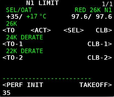
Derates can be assessed on the N1 Limit Page in the CDU. The following derates, applied singly or in combination, are possible:

  • Derated Takeoff Thrust (fixed derate).

  • Assumed Temperature Method (ATM) ; and,

  • Derated Climb Thrust (CLB-1 & CLB-2).

When To Use a Derate

Possible reasons for using or not using a derate are:

  • Environmental considerations (runway condition, weather, wind, etc);

  • Ambient temperature;

  • Airport’s height above sea level;

  • The weight of the aircraft’s load including fuel;

  • Consideration to airline management;

  • The length of the runway; and,

  • Noise abatement.

Electronic Flight Bag (EFB) or Takeoff Performance Tables

A derate is not selected idly by the flight crew. Most airlines use an Electronic Flight Bag (EFB) or another approved source to calculate a suitable derate. If an EFB is unavailable, the aircraft performance data tables in the Flight Crew Operating Manual (FCOM) must be consulted, and the calculations done manually.

Using a derate is not always an option in all situations. For example, in high-performance scenarios, such as heavy takeoffs, high density altitudes, or congested airspace, full thrust may be required. Similarly, a derate may not be suitable if the weather is extremely hot, or if the aircraft is heavy and the runway is short. The final decision on whether to use a derate rests with the Captain of the aircraft.

Thrust Mode Annunciations and Displays

When a derate is used, the thrust mode annunciation (the annunciation is displayed in green-coloured capitals) will be displayed in the Upper Display Unit on the EICAS. The display will differ depending on the airline option.

Possible displays are as follows:

  • TO – takeoff (displayed if no derate is used) - option without derate.

  • TO 1 – derated takeoff 1 - option without double derate.

  • TO 2 – derated takeoff 2 - option without double derate.

  • D-TO – assumed temperature reduced thrust takeoff (ATM) - option with double derate.

  • D-TO 1 – derate one and assumed temperature reduced thrust takeoff (ATM) - option with double derate.

  • D-TO 2 – derate two and assumed temperature reduced thrust takeoff (ATM) - option with double derate.

  • CLB-1 – climb derate.

  • CLB-2 – climb derate.

We will now examine the derates available in the Boeing 737 aircraft.

1 - Derated Takeoff Thrust (Fixed Derate)

A fixed derate is a certified takeoff rating lower than a full rated takeoff thrust. In order to use a fixed derate, takeoff performance data for a specified fixed derate is required (Boeing FCTM 2023). This information is available either from the EFB or from the aircraft performance data tables in the FCOM.

The N1 Limit page in the CDU displays three fixed-rate engine derates: 26000, 24000 and 22000 (26K, 24K and 22K). Selection of a derate will command the software to limit the maximum thrust of the engines to whatever has been selected; nothing is altered on the actual engine. Selecting a derated engine thrust can only occur when the aircraft is on the ground.

Once a fixed derate is selected, it will remain in force until the aircraft reaches acceleration height or a pitch mode is engaged, at which point the fixed derate will be removed.

The N1 for the selected derate is displayed on the NI Limit page, the TAKEOFF REF page (LSK-2L) and in the N1 RPM indication in the Upper Display Unit (%N1 RPM readout and N1 reference bug) on the EICAS.

Thrust Limitation (Fixed Derate)

When using a fixed derate, the takeoff thrust setting is considered a takeoff operating limit. This is because the minimum control speeds (Vmcg and Vmca) and stabiliser trim settings are based on the derated takeoff thrust.

The thrust levers should not be advanced beyond the N1 RPM indication unless takeoff conditions require additional thrust on both engines (e.g., during windshear). If the thrust levers are advanced beyond the N1 RPM indication—such as in the event of an engine failure during takeoff—any increase in thrust could lead to a loss of directional control.

Important Point:

  • A fixed derate can be used on a runway that is either wet, has standing water, or has slush, ice or snow ( provided the performance data supports use of such a derate).

2 - Assumed Temperature Method (ATM)

The assumed temperature method is not exactly a derate; however, it has been discussed because the use of ATM can reduce takeoff thrust.

This method calculates thrust based on a assumed higher than actual air temperature and requires the crew to input into the CDU a higher than actual outside temperature.  This will cause the on-board computer to believe that the temperature is warmer than what it actually is; thereby, reducing N1 thrust. This reduces the need for full thrust, achieving a quieter and more fuel-efficient takeoff.

Using ATM, the desired thrust can be be incrementally adjusted by changing the temperature to a higher or lower value. This can be an advantage to a flight crew as they can fine tune the thrust setting to exactly what is required, rather than using a fixed derate.

ATM is effective only above a certain standard temperature. The 737 Next Generation engines are flat-rated to a specific temperature. In the case of the CFM-56, this is ISA +15°C or 30°C on a standard day. This means the engine can provide full thrust up to that temperature. However, if the temperature exceeds this limit, the engine will produce less thrust. When ATM is used, the temperature must always be set higher than the engine’s flat-rated temperature. Otherwise, the engine will continue to provide full thrust.

Once ATM is selected, it will remain in force until the aircraft reaches acceleration height or a pitch mode is engaged, at which point ATM will be removed.

The desired thrust level is obtained through entry of a SEL TEMP value on the N1 Limit Page (LSK-1L) or from the Takeoff Ref Page 2/2 (LSK-4L).

To delete an assumed temperate the delete key in the CDU should be used.

Thrust Limitation (ATM)

An ATM is not the same as a true derate, even though the takeoff thrust is reduced. This is because when using ATM, the takeoff thrust setting is not considered a takeoff operating limit, since minimum control speeds (Vmcg and Vmca) are based on a full rated takeoff thrust.

At any time during takeoff using ATM, the thrust levers may be advanced to the full rated takeoff thrust (Boeing, 2023 FCTM; 3.17).

Important Points:

  • ATM may be used for takeoff on a wet runway, provided the takeoff performance data (for a wet runway) is used. However, ATM is not permitted for takeoff on a runway contaminated with standing water, slush, snow, or ice.

  • During an ATM takeoff, the yoke may require additional back pressure during rotation and climb.

  • If another derate is selected in combination with ATM, the calculation for takeoff thrust is accumulative. Selecting more than one derate can affect the power that is available for takeoff and significantly increase roll out distance for takeoff.

ATM Annunciations and Displays

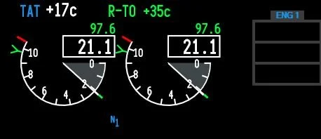
When ATM is used, the temperature used to calculate the required thrust and the calculated N1 will be displayed:

  • In the Thrust Mode Display in the Upper Display Unit on the EICAS (e.g., R-TO +35); and

  • On the N1 Limit page and the TAKEOFF REF page (LSK-1L & LSK-1R) in the CDU.

3. Combined Derate (Fixed Derate & ATM)

A fixed derate can be further reduced by combining it with the ATM. However, the combined derate must not exceed a 25% reduction from the takeoff thrust.

Thrust Limitation (Fixed Derate & ATM Combined)

When conducting a combined fixed derate and ATM takeoff, takeoff speeds consider Vmcg and Vmca only at the fixed derate thrust level.

The thrust levers should not be advanced beyond the fixed derate limit unless conditions during takeoff require additional thrust on both engines, such as in the case of windshear (Boeing, 2023 FCTM; 3.18).

If the assumed temperature method is applied to a fixed derate, additional thrust should not exceed the fixed derate N1 limit. Otherwise, there may be a loss of directional control while on the ground.

4 - Climb Derate (Derated Climb Thrust - CLB-1 & CLB-2) 

There are two climb mode derate annunciations: CLB-1 and CLB-2. CLB refers to normal climb thrust. To enter a climb derate, the N1 Limit page is opened in the CDU. The possible annunciations are as follows:

  • CLB: Normal climb thrust (no derate);

  • CLB-1: Approximately a 10% derate of climb thrust (climb limit reduced by approximately 3% N1; and,

  • CLB-2: Approximately a 20% derate of climb thrust (climb limit reduced by approximately 6% N1).

The use of a climb derate commands the autothrottle to reduce N1 to the setting calculated by the computer for either CLB-1 or CLB-2. The climb derate begins when the aircraft reaches the thrust reduction height (TRH) or during any climb phase up to FL150.

A climb derate can be selected either on the ground or while the aircraft is airborne; however, if during the climb, the vertical speed falls to below 500 feet per minute, the flight crew should manually select the next higher climb rating (for example, change from CLB-2 to CLB-1). As the aircraft climbs, the climb thrust is gradually reduced until full thrust is restored.

It is a common misconception that using a climb derate will minimise the volume of fuel used; however, this is incorrect.

The use of climb thrust does not save fuel; in fact, it consumes more fuel than full-rated takeoff thrust. However, using a lower climb thrust extends engine life and minimises maintenance. Ultimately, the extended engine life and reduced maintenance costs outweigh the additional fuel expense.

To remove a climb derate, either select CLB on the N1 Limit page or use the delete key on the CDU. The latter method is preferred because it deletes the selected climb derate rather than simply unselecting it.

Climb Derate Annunciations and Displays

When a climb derate is used, the derate selected and the corresponding N1 will be displayed:

  1. In the Thrust Mode Display on the Upper Display Unit on the EICAS (the annunciation is displayed in green-coloured capitals);

  2. On the NI Limit page and on the TAKEOFF REF page (LSK-2L) in the CDU;

  3. On the N1 RPM indicator; and,

  4. By the N1 reference bug.

After takeoff, the climb derate will also be displayed on the Climb page in the CDU.

The possible annunciations that can be displayed in the the thrust mode display are:

  1. TO (takeoff without a derate); and,

  2. R-TO (reduced takeoff thrust CLB-1 or CLB-2).

After takeoff, and when the thrust reduction height has been reached, the display will change to whatever climb derate was selected (CLB, CLB-1 or CLB-2).

Important Caveat (all derates):

It is important to note in relation to any derate that the FMC will automatically calculate a corresponding climb speed that is less than or equal to the takeoff thrust. Therefore, a flight crew should ensure that the climb thrust does not exceed the takeoff thrust.

This may occur if a derate or combination thereof is selected, and after takeoff, the flight crew select CLB. Selecting CLB will apply full climb thrust; however, this does not account for any adjustments made by the computer to the initially selected derate. As a result, the climb thrust may be greater than the takeoff thrust.

Boeing Quiet Climb System (QCS) - Abiding with Noise Abatement Protocols

The Boeing Quiet Climb System (often called cutback and referred to by line pilots as ‘hush mode’), is an automated avionics feature for quiet procedures that causes thrust cutback after takeoff.  By reducing and restoring thrust automatically, the system lessens crew workload and results in a consistently less noisy engine footprint, which helps airlines comply with noise abatement restrictions. There are two variables to enter: Altitude reduction and altitude restoration.

During the takeoff checklist procedure, the pilot selects the QCS and enters the height AGL at which thrust should be reduced.  This height should not be less than the thrust reduction height. The thrust restored height is typically 3000 feet AGL, however, the height selected may alter depending on obstacle clearance and the noise abatement required. 

With the autothrottle system engaged, the QCS reduces engine thrust when the cutback height is reached to maintain the optimal climb angle and airspeed. When the airplane reaches the chosen thrust restoration height (typically 3,000 ft AGL or as indicated by noise abatement procedures), the QCS restores full climb thrust.  Note that the minimum height that the QCS can be set is 800 feet AGL. 

The two heights referenced by the Quiet Climb System can be modified in the CDU (TAKEOFF REF 2/2 page (LSK-5R)). The system can be selected or unselected at LSK-6L (on/off).

Multiple Safety Features for Disconnect

The Quiet Climb System (QCS) incorporates multiple safety features and will continue to operate even in the event of system failures. If a failure occurs, the QCS can be exited by either:

  1. Selecting the takeoff/go-around (TOGA) switches on the throttle control levers, or

  2. Disconnecting the autothrottle and controlling thrust manually.

ProSim737

The Quiet Climb System was previously a component of the ProSim737 avionics suite; however, it was removed with the release of version 3.33. It is now available only in the professional version of ProSim737, not in the domestic version.

As a result, if a takeoff requires noise abatement, the necessary calculations and settings must be performed manually. This process is not difficult, as a fixed derate, ATM, or a combination thereof, along with the acceleration height, can be entered or adjusted based on the requirements of either an NADP 1 or NADP 2 procedure.

Figure 2: For completeness, and to provide an example of the altitude above ground level (AGL) that a noise abatement procedure uses.

Figure 2: Noise Abatement Departure Procedures (NADP). (click image for larger view).

Similarity of Terms

When you look at the intricacies of the above mentioned derates there is a degree of similarity.

The way I remember them is as follows:

Derated Takeoff Thrust is when the N1 of the engines is reduced (26K, 24K or 22K). This is done prior to takeoff;

Assumed Temperature Method (ATM) is when the N1 is lowered by changing the ambient temperature to a higher value in the CDU. This is done prior to takeoff;

Climb Derate (Derated Climb Thrust - CLB-1 & CLB-2) is when the N1 used during the climb phase is set to a lower power setting. Selecting a climb derate can be done either prior to takeoff or when the aircraft is airborne; and,

The Quiet Climb System enables a minimum and maximum height to be set in the CDU; thereby, reducing engine power and engine noise.  The restoration height is the height AGL that full climb power is restored.  The QCS is used only for noise abatement.

Final Call

Acceleration height, thrust reduction height, and derates are critical elements in optimising the takeoff performance of the Boeing 737.

Acceleration height is the altitude at which the aircraft’s nose is lowered to gain speed and the flaps are retracted, while the thrust reduction height determines at what height above ground level (AGL) to reduce engine power, from takeoff thrust to a lower setting. By adjusting the engine thrust settings and applying derates, operators can enhance engine longevity, improve fuel efficiency, and reduce noise during takeoff.

Understanding and properly applying these settings not only ensures compliance with performance regulations, but also contributes to operational efficiency. Ultimately, these parameters enable operators to maximise safety, minimise fuel consumption, and optimise aircraft performance during takeoff.

Acronyms Used

  • AGL – Above Ground Level

  • CDU – Control Display Unit

  • CLB-1 & CLB-2 – Climb 1 and Climb 2

  • DERATE – Derated Thrust

  • FL – Flight Level

  • FMC – Flight Management Computer

  • LSK-1R – Line Select 1 Right (CDU)

  • PFD - Primary Flight Display

  • QCS – Quiet Climb System

  • TMD – Thrust Mode Display

  • Vmca – Defined as the minimum speed, whilst in the air, that directional control can be maintained with one engine inoperative.

  • Vmcg – Defined as the minimum airspeed, during the takeoff at which, if an engine failure occurs, it is possible to maintain directional control using only aerodynamic controls. Vmcg must not be greater than V1.

Gallery: Various screen grabs from the CDU showing the effect on %N1 for various fixed derates and Assumed temperate (ATM). 

Acceleration Height and Thrust Reduction Height

Thompson B738NG transitioning to Thrust Reduction Height, Immediately following this will be acceleration height when the aircraft’s nose is lowered, flaps are retracted and climb thrust commences, acceleration will be reached, Manchester, UK (Craig Sunter from Manchester, UK, Boeing 737-800 (Thomson Airways) (5895152176), CC BY 2.0)

The takeoff phase of a flight is one of the busiest and most critical periods, and during this time, several distinct functions occur in rapid succession. While each function serves a unique purpose, they are intricately linked by the changing altitude of the aircraft.

Because they unfold so quickly, these functions often cause confusion for those unfamiliar with the process.

In this article, we will explore the following:

  • Acceleration Height; and,

  • Thrust Reduction Height.

Acceleration Height (AH)

Acceleration height is the altitude AGL that the aircraft transitions from the takeoff speed (V2 +15/20) to climb speed.  This altitude is typically between 1000 and 1500 feet, but may be as low as 800 feet; however, can differ due to noise abatement, airline policy, or airport specifics such as obstacles, etc.

The three main reasons for acceleration height are:

  1. It provides a safe height (AGL) at which the aircraft’s airspeed can be increased (transition to climb speed) and the flaps retracted;

  2. It enables a safety envelope below this altitude should there be an engine failure; engines are set to maximum thrust, and the aircraft’s attitude is set to maintain V2 safety speed (V2+15/20); and,

  3. It provides a noise buffer concerning noise abatement. Below acceleration height the engines will be targeting V2 safety speed (V2 +15/20) and will be generating less engine noise.

Acceleration height can be changed in the CDU: (Init/Ref Index/Takeoff Ref Page (LSK-4—L) ACCEL HT ---- AGL).

Practical Application

Takeoff Ref page showing acceleration height OF 1500 FEET agl and thrust reduction height (thr reduction) OF 800 FEET AGL. BOTH CAN BE CHANGED AS REQUIRED

Once acceleration height has been reached, the pilot flying will reduce the aircraft’s attitude by pushing the yoke forward; thereby, increasing the aircraft’s airspeed.  As the airspeed increases to climb speed, the flaps can be retracted as per the flaps retraction schedule. It is important not to retract the flaps until the aircraft is accelerating at the airspeed indicated by the flaps retraction schedule (flaps manoeuvring speed indicator) displayed on the speed tape in the Primary Flight Display).

Assuming an automated takeoff with VNAV and LNAV selected, and once acceleration height is reached, the autothrottle will be commanded by the autoflight system to increase the aircraft’s airspeed to climb speed. If manually flying the aircraft, the flight crew will need to increase the speed from V2 +15/20 to climb speed (by dialling a new speed into the MCP speed window).

Although crews use slightly varying techniques; I find the following holds true for a non-automation climb to 10,000 feet AGL:

  1. Set the MCP to V2;

  2. Fly the flight director cues to acceleration height (this will be at V2 +15/+20);

  3. At acceleration height, push yoke forward reducing the aircraft’s attitude (pitch);

  4. Dial into the MCP speed window the appropriate 'clean up' speed (reference the top white-coloured carrot on the speed tape of the PFD, typically 210-220 kias);

  5. As the forward airspeed increases, you will quickly pass through the schedule for initial flap retraction (as indicated by the green-coloured flaps manoeuvring speed indicator – retract flaps 5;

  6. Continue to retract the flaps as per the schedule; and,

  7. After the flaps are retracted, engage automation (if wanted) and increase airspeed to 250 kias or as indicated by Air Traffic Control.

Note:  If the acceleration height has been entered into the CDU, the flight director bars will command the decrease in pitch when the selected altitude has been reached - all you do is follow the flight director bars.

upper display unit (in eicas) showing Thrust reduction. the green-coloured N1 reference bug reads 89.8 N1 and takeoff thrust is being reduced to this figure from 97.8 N1

Thrust Reduction Height (TRH)

The main wear on engines, especially turbine engines, is heat. If you reduce heat, the engine will have greater longevity. This is why takeoff power is often time limited and the thrust reduced at and a height AGL. The difference between takeoff thrust and climb thrust may vary only be a few percent, but the lowering of EGT reduces heat and extends engine life significantly. 

The thrust reduction height is the height AGL where the transition from takeoff to climb thrust takes place.  Acceleration height comes soon after.

The height used for thrust reduction, not taking into account noise abatement, can vary and be dependent on airline policy. Typically it falls between 800-1500 feet AGL. 

Possible reasons for selecting a higher height AGL at which thrust reduction occurs may be obstacle clearance (such as buildings, towers, etc) or environmental factors.

When the aircraft reaches the thrust reduction height, the resultant loss of N1 is displayed on the N1 RPM indication in the Upper Display Unit of the EICAS. The N1 is displayed in large white numerals (87.7) and is also indicated by the green-coloured N1 reference bug.

Confusion between Acceleration Height and Thrust Reduction Height

Newcomers are often confused between the two similarly-sounding terms, possibly because they both occur at the interface between takeoff and climb-out.  Simply written:

  • Thrust Reduction Height is the height AGL at which the takeoff thrust will be reduced by a few percent N1. This is done to increase engine life and lower maintenance. It is alos when the autothrottle will be commanded to decrease the takeoff thrust to climb thrust; and.

  • Acceleration Height is when the nose of the aircraft is lowered to increase airspeed. The flaps are then retracted as per the flaps retraction schedule.

    Both may occur simultaneously or at differing heights above ground level.  Both can be configured in the CDU.

To change the acceleration height: Init/Ref Index/Takeoff Ref Page 2/2 (LSL-4L).

To change the thrust reduction height: Init/Ref Index/Takeoff Ref Page 2/2 (LSL-5R).

Final Call

Acceleration height and thrust reduction height are critical elements in optimising the takeoff performance of the Boeing 737.

Acceleration height is the altitude at which the aircraft’s nose is lowered to gain airspeed and the flaps are retracted, while the thrust reduction height determines at what height above ground level (AGL) to reduce engine power, from full takeoff thrust to a few percent less N1. The lowering of N1 enhance engine longevity, improve fuel efficiency, and reduce noise during takeoff.

Note

This topic previously was part of another multi-faceted article. To improve readability it has been separated out from the original.

BELOW: Video showing thrust reduction height and acceleration height (ProSim737).


Takeoff (derate 24K CLB-1). Note drop in N1 thrust as aircraft reaches 800 feet AGL (throttle reduction height). At acceleration height (1500 feet AGL) the flight director commands a pitch down. As airspeed increases flaps are retracted as per the schedule (ProSim737)


Changing-out Potentiometers - UniMeasure LX-PA Series Position Transducer

UniMeasure LX-PA string potentiometer secured to a bespoke L-bracket and mounted on a board beneath the platform. The string connects with the rudder assembly

Potentiometers are arguably one of the most critical components in a flight simulator.  Without a potentiometer, the accurate calibration of the flight controls (or any other device) isn’t possible.  

Over the years, I have used a number of different types of potentiometers, beginning with inexpensive Chinese-made linear and rotary types, and later progressing to Bourns rotary potentiometers paired with fabricated strings. At one point, I also trialled a commercial CALTSensoR string potentiometer.

When a string broke on the potentiometer that controlled the elevator, I decided that, rather than repair the string, I would replace all the potentiometers used to calibrate the flight controls (ailerons, elevator and rudder).

Instead of using the CALTSensoR model mentioned earlier, I opted to upgrade all the potentiometers to string potentiometers made by UniMeasure.

UniMeasure Potentiometers (Transducers)

UniMeasure, an American company based in Oregon, specialises in manufacturing position and velocity sensors for the medical, defence, and industrial sectors. Renowned for their high-quality components, UniMeasure potentiometers adhere to Mil-Spec and IP/NEMA standards, and they’ve been an industry leader since 1987.

After reviewing the different types of potentiometers, I ordered three LX-PA series position transducers.

Is it a Potentiometer or a Transducer

The terms potentiometer and transducer are often used interchangeably to describe the same component.  Although the use of these terms is acceptable, there are subtle differences between a potentiometer and a transducer.  The primary difference being that a transducer will convert the input received into a different output, whereas a potentiometer will only detect and measure the movement of an object (for example, a control arm).

LX-PA Series Position Transducer

The LX-PA series transducer consists of three main parts:

  1. A potentiometer – a Bourns rotary potentiometer (type 3545).

  2. A retractable mechanism – a reel so that the string can extend and retract.

  3. A string – a 0.4 mm jacketed stainless steel length of wire with a stainless steel eyelet.

These components are housed in a compact, durable ABS plastic casing.  The small size and lightweight design make the LX-PA ideal to use in relatively tight spaces.

How the LX-PA Series Transducer Works

Before installing and using a string potentiometer, it’s important to have an understanding of how a potentiometer works.

A potentiometer is a resistive-type transducer, that converts linear or angular displacement into a variable voltage output signal. This process occurs when a sliding contact (known as the wiper) moves along the surface of a resistive element, typically a carbon track.

The potentiometer is securely mounted at a fixed position, with its string attached to a movable object. As the object moves, the string extends, rotating the internal sensing device to produce an electrical output proportional to the object’s position or velocity.  An internal spring maintains string tension and serves as the retraction mechanism for the string.

Electrical Output

The electrical output that is produced by the potentiometer is less effective as the string reaches its fully retracted or extended position, meaning that calibration is not as effective towards each end of the string’s length.  Therefore, it is important to take into consideration the length of the potentiometer’s string. 

LX-PA string potentiometer mounted to L-bracket and secured to platform. The string can be seen in a direct line connecting with the ailerons

Measuring the Throw

To ensure optimal results, measure the throw from the mounting point of the potentiometer to where the end of the string is to be attached to the moveable object, then add a few inches to your measurement.  This is the length of string that should be used with the potentiometer. 

If the string is too long or short, you will be calibrating the end points of the string, which is not as accurate as if you had calibrated the central portion of the string.  Additionally, if the string is too long and near its end point, excessive tension on the reel’s retractable mechanism may occur, leading to premature loss of tension.

An average rule of thumb is to try and use two thirds of the distance (throw), or predominately the central portion of the string, as this is where the most effective output signal is found, and where the best calibration can occur. 

When you order a potentiometer from UniMeasure, you inform the technician of the length of the string required and the potentiometer is made to your specification.

It is important to note that potentiometers are passive components, meaning they do not necessitate a power supply or additional circuitry to operate.

Important Point:

  • The length of the string is important. However, do not be overly pedantic about obtaining the exact measurement. The calibration will still be accurate provided you allow a few extra inches (a ‘dead zone’) at each end of the string, and primarily use the central portion of the string.

Splitter ring attached to tilt elevator mechanism of the flight controls with the lobster clasp connected

Installation and Attachment

Although the LX-PA series is not the smallest potentiometer UniMeasure manufactures, it is small enough to be mounted in all but the tightest areas. 

The potentiometer requires a secure attachment point, and a bracket is the easiest way to do this.  UniMeasure sell a dedicated bracket, however, I decided to fabricate my own L-bracket.  The LX-PA has two 5 mm diameter holes in the body of the potentiometer and can be secured to the L-bracket by a suitable bolt and nut.  The position of the holes in the main body enable the potentiometer to be mounted a number of ways (up, down, inverted, sideways, flat, etc).

To attach the string to the moveable object (aileron, elevator rudder, etc) requires that there be a stable attachment point on the object.  The string does not have to be permanently attached to the object (although you can do this). 

Splitter Ring and Lobster Clasp

My preferred method is to attach to the eyelet of the string to a one way clasp (often called a lobster clasp).  This clasp is attached to a splitter ring (curtain-rail ring) that is attached to the object. To enable attachment of the splitter ring, I have drilled a hole into a moveable part of the flight control mechanism.

The advantage of using a lobster clasp is the string can easily be disconnected; for example, when servicing is required.

Line Pull

The direction of the line pull is important and UniMeasure recommend to not exceed 2 degrees in any direction.  If a further offset is required, a stand-off, such as a fly wheel, will need to be purchased or fabricated.   

Exceeding the recommended offset will more than likely shorten the life the string, because the string would retract into the spool at an angle, causing undue wear and tear with a potential loss of accuracy.

Important Points:

  • For the string to be effective, the string must be under tension.

  • Do not extend the string to its full length, as this can damage the reel mechanism.

  • Maintain lateral or vertical alignment within 2 degrees to avoid unnecessary wear on the reel.

  • Do not allow the string to come into contact with objects along its path.

Connection and Calibration

It is not difficult to connect the UniMeasure potentiometer to the computer.

The wires from the potentiometer are connected to the appropriate input on a joystick interface card, such as a Leo Bodnar BU0836A or BU0836X joystick card.  Previously I used the former, but changed-out to the larger BU0836X card as it was easier to connect the wires to the card. 

One difference between UniMeasure potentiometers and others is that the UniMeasure has one additional wire to the standard three.  The forth wire is a shield wire (naked coiled wire). 

What is a Shield Wire

A shield wire provides electromagnetic compatibility protection and serves two purposes:

  1. It prevents interfering signals from the inside of the cable from reaching the outside and being disturbed to other cables and electrical devices; and.

  2. It ensures that external interference does not reach the inside of the cable and potentiometer.

Shield wires are often connected when a potentiometer is used in a high-accuracy setting such as in medical scanners.  However, it is debatable if there is any positive benefit in using a shield wire in a flight simulator environment. If the shield wire is used, the wire should be connected to ground for optimal results.

The other three wires from the potentiometer: common (black wire), +5 Volts (red wire) and the output (white wire) connect to the respective points in the BU0836X card.

All the wires have been professionally soldered to the potentiometer’s terminals, and are insulated with PVC, except for the last 4 cm which are bare. 

Calibration of the potentiometer requires initial registration in Windows using the joystick controller interface (type JOY in the computer’s search bar).  After this has been completed, calibration can be done either directly in flight simulator, ProSim737 or FSUIPC.

Protection from Dust and Water

The LX-PA series is not fully dust-proof or waterproof.  Whilst the potentiometer itself is dust-proof due to its enclosed design, dust can accumulate where the string enters the reel.  This said, unless the string is located in a particularly dusty environment, dust ingress should not occur.  If dust does present a problem, the string can be cleaned using high-pressure air, alcohol, or a circuit-board cleaner. 

If the environment is particularly dusty or damp, an alternative UniMeasure series potentiometer should be considered that has better dust-proofing.

Interestingly, the method used by UniMeasure to dust-proof their potentiometers (not the LX-PA series) involves the use of two curtains that are installed where the string slides into the mechanism.  These curtains when dirty, can be removed for cleaning or can be replaced. 

To protect the potentiometer’s terminals where the wires are soldered, UniMeasure offers a removable cover.  The cover pushes over the cylindrical part of the potentiometer and is secured by three small screws.  The cover ensures that nothing will damage the terminals.  The cover is a very good fit and it is very unlikely that any dust or moisture will enter behind the cover into the potentiometer

Durability and Lifespan

The body of the LX-PA series is made from ABS plastic, and when the potentiometer is fitted with the protective cover (discussed earlier) makes for a relativity robust unit; an odd light knock here and there is not going to damage the potentiometer.

The LX-PA transducer has an impressive lifespan:

  • The potentiometer is rated for 2.5 million cycles, while

  • The lifespan of the reel and string varies and is dependent upon length of the string:

    • Up to 4.7 inches - 1,000,000 cycles.

    • 10–25 inches - 250,000 cycles.

Accuracy and User Experience

Although the LX-PA transducer uses a standard Bourns potentiometer, the accuracy when calibrating and using the potentiometer comes more from the build quality of the string and how it retracts into the reel, than the actual potentiometer. 

The slightest movement of the yoke, elevator or rudder is reflected in the avionics software and there is no noticeable acceleration or lag as the string moves in and out of the of the reel.   In comparison to its closest rival, the CALTSensoR potentiometer, the UniMeasure string’s movement is far more smooth and has no apparent binding.

Calibrating flight controls to ensure optimal accuracy has always been finicky, and considerable time can be wasted attempting to achieve optimal results. Calibration of the LX-PA potentiometers was a breeze, and since using these potentiometers I have noticed that control of the aircraft, especially during crosswind landings, is far more easy than what it previously was.

Additional Information

Final Call

The LX-PA series transducer is a premium potentiometer that combines a high-quality Bourns rotary potentiometer with a durable, precision-engineered retractable reel and string.  With proper calibration, it captures even the slightest movement with impressive accuracy, making it a perfect choice to connect to the flight controls.

Below: UniMeasure LX-PA series potentiometer

Changing-out Joystick Cards - Leo Bodnar BU0836X Joystick Card

Leo Bodnar BU0836X joystick card and enclosure

Most flight simulators require regular maintenance to ensure that all systems function correctly. During a routine overhaul, which included replacing the potentiometers that are used to calibrate the flight controls, it was discovered that a Leo Bodnar joystick card had been damaged. Rather than replace the card with the same type (BU0836A), I decided to change-out to a Leo Bodnar BU0836X joystick interface card and protect it with a dedicated metal enclosure. 

I will not duplicate the detailed information that has already been written about the BU0836X on the Leo Bodnar website.   Rather, I will examine the advantages of using this particular card. 

The card and its protective enclosure can be purchased separately from Leo Bodnar Electronics in the United Kingdom. 

BU0836A and BU0836X Joystick Card

The BU0836X 12-bit joystick interface card has been available for some time and is very similar to the BU0836A joystick card; the latter being the mainstay for interfacing various hardware.  Both cards enable calibration of the joystick axes used for controls such as the ailerons, elevator, rudder, and the steering tiller, as well as interfacing with a various simulator buttons and knobs. 

Key Advantages 

The primary advantage of the larger BU0836X card, aside from its additional inputs and outputs, is that it does not use the JR connectors found on the BU0836A card.  JR connectors can be fiddly, prone to breaking (if not connected properly), and may become loose unless soldered directly to the card’s pins.

Over the years, I and cannot recall how many times a JR connector had worked its way loose from the vibration generated by the trim wheels rotating, and depending on the location of the card, a repair can be time consuming.

In contrast to using JR connectors, the BU0836X features push-to-secure connectors. This design allows wires between the gauge of 24-20 AWG (stripped to 9mm) to be easily inserted into the correct terminals and locked in place without requiring screws, solder, or JR connectors.  It’s only a matter of pushing the tab on the card inwards and inserting the wire into the hole. 

The push-to-secure design not only simplifies connection but also makes it easier to replace components like potentiometers or other hardware devices when necessary.  Additionally, the terminal bar is colour-coded with clearly printed labels, making identification straightforward, thereby reducing the risk of wiring errors.

The card has 8 analogue inputs (potentiometers, knobs), 32 inputs (button, switches) and 1 joystick HAT controller.

I find that working with a slightly larger card is much easier than its smaller sister, although an obvious downfall is the space required to mount the BU0836X card. I also like the fact that the card is made in the United Kingdom; therefore, production inconsistencies that occur with many less expensive Chinese cards is not as prevalent.

BU0836X Protection 

The card can be mounted on a base plate using standoffs and screws.  However, as with any hardware component, it is susceptible to damage from movement, accidental knocks, or falling objects - especially during maintenance (screwdrivers, pliers, eye glasses, coffee cups, mobile phones, i-pads, etc). 

To address this, Leo Bodnar offers a protective enclosure that has been specifically designed for the BU0836X and BU0836A cards respectively. The enclosure comprises two pieces of metal with the inner piece (called the slider) designed to slide into and out of the outer casing.  The card clips firmly into the inner slider and a small hex screw fastens the slider into the outer casing.  Realistically, the hex screw is overkill as the inner slider fits quite firmly, and I very much doubt that the slider will accidentally slide out of the outer casing.  The enclosure can then be attached to a base plate using four screws.

Once secured inside the enclosure, the card remains firmly in place and does not move or wiggle, ensuring excellent stability. This setup provides robust protection against physical damage while keeping the terminals fully accessible.

The enclosure has been well designed, is fabricated from metal, powder coated, and coloured black.

Additional Considerations 

Despite the protective enclosure, the wiring remains exposed to the environment, leaving it vulnerable to dust and dirt accumulation.  If this is a concern, a simple and effective solution is to fabricate a small plastic cover to shield the card and its wiring.  A repurposed plastic takeaway container works well for this purpose, providing an inexpensive and practical way to keep the card clean and secure. 

Calibration

The BU0836X card is calibrated in the same way as the BU0836A card: initial registration in windows using the Game Controller (type JOY in the computer’s search bar) and then calibration in either flight simulator, ProSim737 or FSUIPC.

Final Call

The BU0836X card stands out for its well-thought-out design. Its larger size makes terminal identification and access easier, while the push-to-secure connectors provide reliable, solder-free connections.  Although its size could be a disadvantage in tighter spaces, it works well for most applications where space constraints are not a concern.  Additionally, the optional metal enclosure offers protection against physical damage, enhancing the card’s long-term durability.

For further information detailing how to use the BU086X joystick card.

  • This article is not endorsed by Leo Bodnar Electronics. Furthermore, I paid full price for the products discussed. 

Below: Gallery showing photographs of the BU0836X and BU0836A joystick cards and enclosures.