Commercial Rotary-String Potentiometer Review

Commercial Rotary-String Potentiometer Review

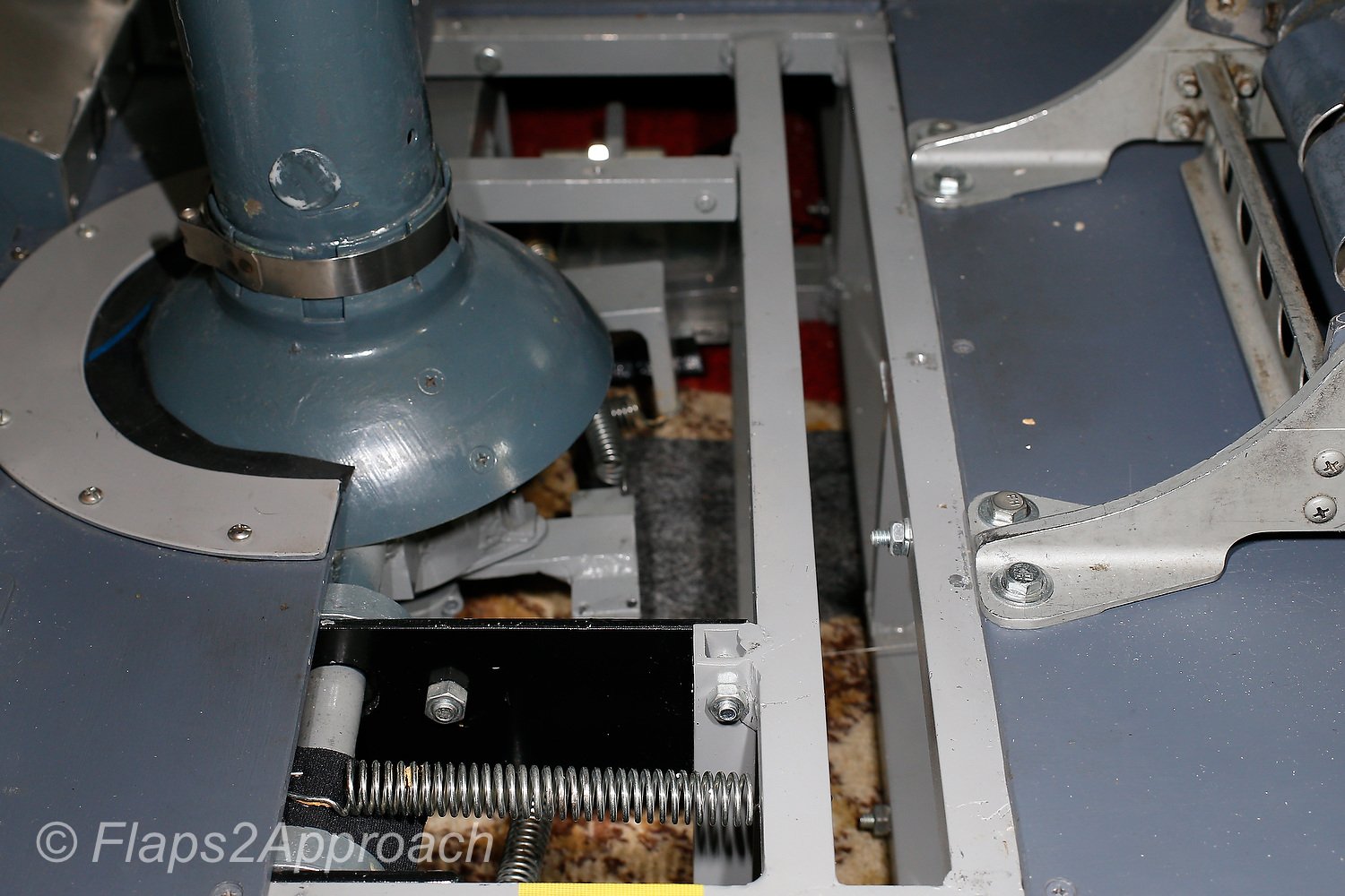
Recently, whilst on a final approach I heard a ‘twang’ followed by loss of aileron control.  I knew immediately what had happened; the tensioned stainless steel string from the string potentiometer had snapped and the wire had retracted into the mechanism. 

Read More

Fabricating a String Potentiometer

Bespoke string potentiometer

String potentiometers are fast becoming the mainstay for those wanting to obtain accurate outputs when a lever is moved, such as the: ailerons, elevators, rudder, flaps, speedbrake, or thrust levers in the throttle quadrant.  This is because the slightest movement of a the string is registered by the potentiometer.

While commercial made string potentiometers can be purchased, they are not inexpensive, and if used will deliver an order of accuracy that isn’t necessary for the assigned tasks.

In the example discussed I I am not using a commercial string potentiometer.  Rather, a standard Bourne 3500-3501 rotary potentiometer has been adapted to use a string.

Requirements

You will need the following items:

  1. Bourne rotary potentiometer;

  2. Plastic housing box;

  3. 6 screws (to secure box lid and to fasten spool);

  4. One nut and washer (to secure potentiometer to box)

  5. A retractable spring-loaded spool and stainless steel ot nylon string;

  6. A cylindrical piece if moulded ABS plastic (or wood); and,

  7. A small dog leash type clip or other fastening device (not pictured).

It’s best to use a CNC machine to fabricate the correctly shaped box, however, any box can be used.  Boxes can be purchased from electronic shops that are used as a housing for interface cards.  These are suitable.

It’s difficult to document exactly how the process is done, but by carefully studying the pictures, you should be able to replicate the process.

Fabrication

  1. Make a small hole in the side of the box for the string.  Ensure the hole enables the string to have some lateral movement.  You may need to attach some type of protection to the inside or outside of the hole so that the string doesn’t rub the plastic.  I have used a soft piece of plastic for this task (Figure 1).  Equally suitable is piece of cork (wine bottle)

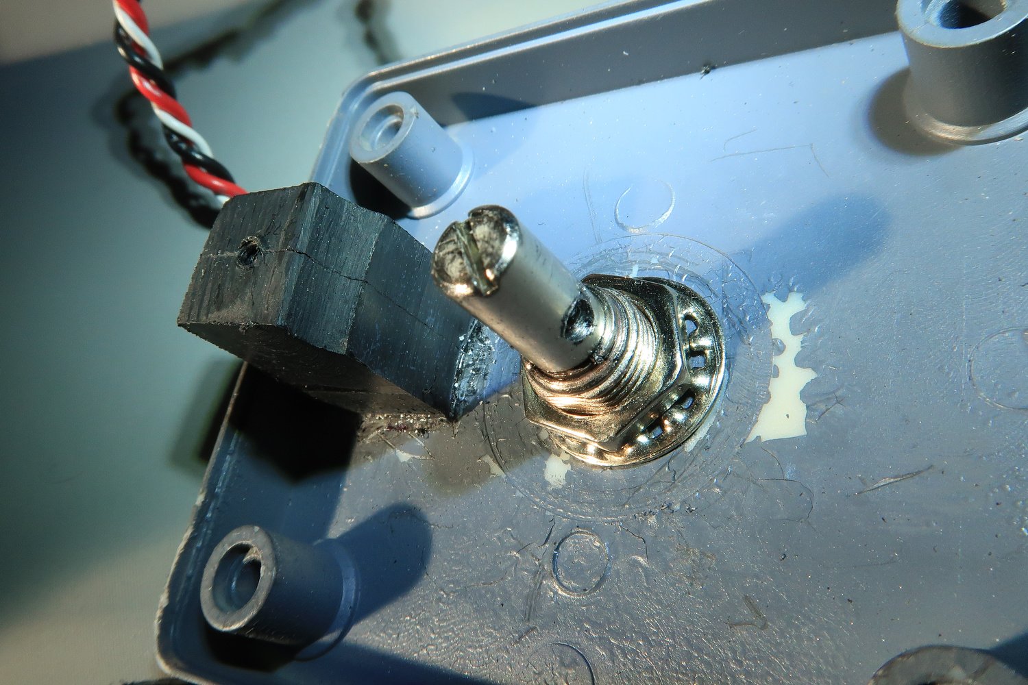
  2. Drill a circular hole in the top of the box to enable the shaft from the potentiometer to be inserted.  Secure the shaft with a nut and washer (Figure 2).  The main body of the potentiometer will be outside the box.

  3. Glue a piece of solid ABS plastic (or wood) to the lid of the box.  Make a small drill hole that enables a screw to be attached.  This screw is used to help secure the retractable spool (Figure 2, 4 & 6).

  4. You must fabricate, from a piece of ABS plastic or similar, a cylindrical attachment that is glued to the retractable spring-loaded spool.  This piece if plastic must a hole drilled that is the same circumference as the shard of the potentiometer (Figure 3).

  5. The retractable spring-loaded spool is glued to the bottom of the box in direct line with the shaft of the potentiometer.  The shaft must align with the hole in the spool (Figure 1).

  6. Drill a small hole into the side of the shaft of the potentiometer and the retractable spool.  The hole should be large enough to enable a small screw to secure the retractable spring-loaded spool to the shaft.  This is done to stop the spool from freely spooling.  When it’s secured, the string when pulled in or out will turn the shaft of the potentiometer (Figure 2, 3 & 6).
  7. When everything is complete, the string should move the shaft of the potentiometer as it is pulled out of the retractable spring-loaded spool.  To secure the spring to the control device, a small clip can be used which is attached to the end of the string.  I have used a small dog leash style clip, but any clip will work.

Photographs

The fabrication as seen in the gallery photographs appear quite rough.  This is because the example photographed was a prototype.  If you are carefully, work methodically, and have an eye for detail, then there is no reason why the end product will not look semi-professional.


Updating Firmware to Leo Bodnar BU0836A 12-Bit Joystick Controller and Button Box BBI 32/64 Cards

BUO0836A Joystick Controller card with wires from the string potentiometer (ailerons)

Nearly every flight simulator has hardware devices that need to be connected to the server computer, whether it be to control the buttons and levers on the throttle quadrant, flight controls, or any other add-on device.

Most enthusiasts can recall a time when they experienced a problem with a hardware device.  Perhaps the device couldn’t be calibrated, or when calibrated, the settings were not maintained.  Worst case scenario was the device didn’t function and wasn’t recognised by the computer.  Many of these potential problems can be minimised by ensuring that the firmware on the card is the latest version release.

In this article, I’ll discuss how to update the firmware the BU0836A 12-Bit Joystick Controller card.  The same process can be completed to also update the Button Box BBI-32 or 64 card.  Both cards are manufactured by Leo Bodnar Electronics.

Background

To connect a device to the computer, so that it can device can be recognised by Windows (and subsequently ProSim737 and flight simulator), requires an interface card of some description.  

Often, there isn’t much thought to addressing the firmware for the selected card.  The premise is if it works leave the card alone, and often this is the case, until you purchase replacement computer, upgrade your operating system, or install updates to the operating system.  Then, all of a sudden telltale symptoms emerge such as calibration issues, or in the worse case scenario, the computer fails to recognise the card.

Firmware

Any advanced interface card requires firmware.  The firmware at its simplest, is a basic set of instructions to enable the card to communicate with the computer’s operating system (think double helix, chromosomes and DNA). 

When a card is purchased, the firmware is usually up-to-date so that the card will function with the latest operating system.  However, with time many aspects relating to the computer change (hardware, drivers, operating system, etc).  However, rarely is the firmware on the card updated.  Some manufacturers don’t update the firmware; instead preferring to sell another card.  However, a reliable manufacturer will nearly always offer upgraded firmware, from time time, especially after a period of time in which there has been major evolutionary computer change (for example, WIN XP/7 to WIN10).

At the time of writing, the latest release for the BUO086 card was Version 1.26.

Screen grab of the User Interface from the HID flash tool

Upgrading Firmware (flashing)

The process of upgrading the firmware on either of the above-mentioned cards is  called ‘flashing’, and if done correctly is a straightforward process. 

Prior to a card being flashed, it’s necessary to download (from the Leo Bodnar website) the HID flash tool and the firmware versions for the card.

The flash tool is a standalone program and is used to read any Leo Bodnar card connected to the computer.  Once a card has been read by the software its firmware version number can be ascertained.

Important Point:

  • The latest version of the firmware for the BU0836A and BBI cards, and the HID flash tool, can be downloaded from the Leo Bodnar website (towards bottom of page).

Important Suggestions:

  • Do not install the HID flash tool to the computer used by flight simulator.  Rather install the program to another computer.  Disconnect the card requiring flashing from the flight simulator computer and reconnect this card to the second computer.

  • Only connect one card at a time to the computer.  Looking at multiple cards simultaneously can be confusing, and you may inadvertently ‘flash’ the wrong card.

  • Always try and use the shortest USB cable possible when flashing a card.

How To 'Flash'

In this example, we will discuss upgrading the firmware to a BU0836A Joystick Controller card.  The process is identical for the BBI 32/64 cards.  As this article is quite short, including diagrams is difficult.  Therefore, a copy of the instructions including screen grabs can be downloaded in the Documents Section.

1:  Download the HID flash tool and firmware version zip files from the Leo Bodnar website and unzip the files to your desktop.

2:  Connect the Leo Bodnar card to the computer and open the HID flash tool as Administrator (mouse right click/open).  The software will open at the User Interface that displays various information for the selected card.  Take note of the firmware version number.  If it’s the latest firmware, then there is no need to flash the card (unless you suspect a problem with the firmware).

3:  If more than one card is listed, select the correct card and click the 1. Bootloader tab.  This will place the card into flash mode.  The interface will display the word boot or bootloader.

4:  Click the 2. Browse file tab and navigate to where you downloaded the various firmware versions.  Select the correct firmware upgrade version.  The firmware is documented as .bin files.  I am told that all the bin files are identical, other than the number (more on this later). 

5:  Once the file is selected, click 3. Flash firmware.  The firmware will be flashed to the new version.

Important Points:

  • If it’s not possible to update the firmware (old or damaged card), then the User Interface will indicate the card is still in boot or bootloader mode.  In  this case, an updated card will need to be purchased.

Renaming Cards

if you use mulitple cards.  Flashing can be a good way to change the name of the card to avoid confusion when looking at the card names in ProSim737.   Therefore, in Point 4 above, if you use .bin3, the card will be renamed to BU0836A_3 and if you choose .bin7, the card name will be BU0836_7 (and so forth).

Calibration Settings

It’s not uncommon for some calibration settings to be lost when a card is flashed.  Whether the settings are lost, depends upon how the card was used in the first place.  It's very likely the various axis will require re-calibration (ailerons, elevators, trim wheel and rudder), however, button settings should remain stable (because buttons are on/off and are connected to the terminals on the card).

Final Call

Computer hardware, operating system, and Windows updates can cause problems with various interface cards, especially if these cards are dated.  Fortunately, many manufacturers offer firmware that can update the card to enable it to operate flawlessly with a new up-to-date system.

Additional Information

Corruption of joy.cpl File Leading to Problems With Registration and Calibration in Windows 10

Every flight simulator uses input devices, and these devices must be initially registered and calibrated in the Windows Operating System, prior to advanced calibration in ProSim737 or FSUIPC.

Occasionally, the User Interface used to register and calibrate the devices fails or crashes.  One potential reason for the interface becoming unresponsive, can be caused by Windows 10 updates, that are automatically downloaded and installed to your computer.

While most updates are benign, some will tamper with settings that otherwise were thought to be ‘set in stone’.

In this article, I’ll discuss how the corruption of the joy.cpl file can lead to problems when attempting to register and calibrate joystick controllers.

Note that I use the word input device, game controller, joystick controller, and hardware device interchangeably.  Also be aware that the joy.cpl file is used in all late Windows operating systems (XP onwards).

Background

Flight simulator uses several hardware devices.  A basic list of the most commonly used is listed below:

  • Flight controls (aileron, elevators, steering tiller, rudder).

  • Yokes (buttons and elevator trim).

  • Throttle Quadrant (buttons, flaps lever, speedbrake lever, thrust levers, cut-off levers, parking brake).

Often, but not always, the items mentioned above are connected to the computer by a Leo Bodnar Joystick Controller or Button Box card (BU0836A and BBI-64 or similar).  These cards must be registered, and the connected potentiometers calibrated in Windows, prior to more advanced calibration in ProSim737 or FSUPIC.

Registration and calibration occurs in the Windows Joystick Calibration User Interface (Game Controller Interface).

It's often easier to think of calibrating controls as a two-stage process - Primary Registration and Calibration (in Windows) and Secondary Calibration (in Prosim737, flight simulator, or FSUPIC).

Joystick Calibration User Interface displaying opening menu and calibration menu

Registration and Calibration (Primary Calibration)

By way of an example, let’s assume a yoke is being connected to the computer via a Leo Bodnar BU0836A 12-Bit Joystick Controller card.   The movement of the ailerons and elevator (potentiometers) will need to be initially registered and calibrated in Windows.

To begin the registration process, open the Joystick Calibration User Interface and follow the prompts.  During the registration and calibration process, each of the end points for the movement of the potentiometer will be recorded, and an axis assigned to the aileron and elevator.  Initial calibration of each axis then occurs.  This information is saved into a file called joy.cpl.  

Important Point:

Calibration of any axis must involve moving the hardware device as far as possible (left, right, forward or backward).  This ensures that the full range of movement from the potentiometer is recorded during the registration process. 

A .cpl file is a .DLL file that stores information for other programs to access.  It’s part of the game controller applet and creates an entry in the Windows registry.  I don’t want to dwell any longer than necessary on the Windows infrastructure, as this information is readily available from the Internet.

Handy Shortcut:

  • There are several ways that the User Interface can be accessed: press 'WIN key and R' and then type either ‘joy’ or 'joy.cpl' into the search bar.   Another way is to type ‘joy’ or 'joy.cpl' directly into the Cortana search bar (Windows 10).

Corruption of joy.cpl File.

Initially you may not realise there’s a problem, until you discover it’s not possible to calibrate a device accurately in ProSim737 or in FSUPIC.  Or, if registering a new hardware device, the registration and calibration fails.  Corruption of the joy.cpl file will usually cause the Game Controller Interface to crash.

How the joy.cpl file becomes corrupted is unknown (by me).  I’ve read that Windows updates to sound drivers can sometimes cause an issue.  However, when I recently experienced a problem when attempting to register a new joystick controller card, removing and replacing the sound drivers didn’t rectify the problem.  

The Solution

Thankfully, the solution to this problem is relatively straightforward.  The joy.cpl must be deleted and replaced with a fresh copy.  

Important Points:

  • The corruption of the joy.cpl file is one of the most common reasons for registration and calibration problems, however, it may not be the only reason.

  • While Windows 10 updates can cause corruption of the joy.cpl file, there are other reasons that may cause this file to be corrupted.

Screen grab of the Sytem32 folder showing joy.cpl file

How to Repair the joy.cpl File

Rectifying the problem is a two-part process involving deleting the  joy.cpl file and replacing it with a fresh copy (non-corrupted) copy.

The joy.cpl is located in the Windows System32 folder (C:\Windows\System32).

Each computer system is slightly different, and depending on the file’s protection status, deleting the file may be difficult.  When attempting to delete this file, always log in as Administrator.  

If the file still can’t be deleted, a standalone unlocking program will be required.  As the name suggests, this program ‘unlocks’ the file (or any other file selected) so that it can be deleted.  There are several free unlocking programs available from the Internet.  I used a program called UnLocker.

Install UnLocker to the computer and follow the prompts after which the joy.cpl file should be able to be deleted.

Next, open the SysWOW64 folder (C:\Windows\SysWOW64).  Scroll downwards and find the  file joy.cpl file.  This is a copy of the file keep by Windows.  COPY this file and paste it into the System32 file.

After this has been done, registration and calibration of any hardware device should be possible.

Important Points:

  • It’s standard practice to always make a copy of any file prior to deletion (so you can rollback if necessary).

  • Always COPY the file from the SysWOW64 folder.  NEVER cut and paste.

  • When you replace the joy.cpl file, any settings previously held in registration may no longer exist.  If this occurs, registration and calibration will need to be done again for ALL hardware devices.

Backup Configuration Settings

The file that contains the configuration settings is the joy.cpl.

This file contains the information Windows needs to be able to load the settings obtained during Primary Calibration.  This file should be backed up.

Important Point:

  • If a problem develops at some point, it's an easy matter to replace the joy.cpl file with the backed up copy.  if the problem persists, then replacement of the file (from the SysWOW64 folder may be necessary).

Although Secondary Calibration has not been addressed in this article, it's recommended to backup these settings (included for completeness).  Recommended files to backup.

  • C:\Users\Your_Name\AppData\Roaming\Lockheed Martin\Prepar3D v4\Controls\Standard.xml, controls.xml and/or joysticks.xml

  • P3Dv4\modules\FSUIPC.ini

  • Prosim737\config.xml (located in ProSim737 main system folder)

  • C:\Windows\System32\joy.cpl.

Final Call

Not being able to register a hardware device in Windows can be frustrating and time consuming.  The registration and calibration information of any hardware device is recorded in the joy.cpl file.   If this file is corrupted, initial registration and calibration of hardware devices won’t be possible.  Prior to troubleshooting elsewhere, the first point of call should be to delete the corrupted file and replace it with another copy.

Using a Pololu JrK Card to Fine-tune the Calibration of Thrust Levers

OEM NG style thrust lever

The throttle quadrant for many enthusiasts is the ‘holy grail’ of the simulator, and many individuals strive to ensure that the throttle operates as close as possible to its real world counterpart. 

The automated systems in the 737 aircraft drive the movement of the thrust levers in a coordinated manner, and it’s the accuracy, speed, and  synchronised movement that enthusiasts try to replicate.

Historical Context

Individuals often use Leo Bodnar Joystick cards, PoKeys, Arduino, and Phidget Advanced Servo cards to interface the throttle quadrant (and other hardware) with some using SIOC (a programming language) to connect propriety throttle quadrants.  Calibration, more often than not, was done via FSUPIC, or in a rudimentary way through ProSim737.

Although the throttle quadrant functioned, the position of the levers didn’t match the correct position for the commanded thrust (%N1), and the thrust levers would often be offset against each other and not move in a synchronised manner.  These shortcomings lead to the throttle being used only in ‘manual mode’, as the feedback from the software to the throttle didn’t generate consistent and reliable results. 

Two innovations have changed this – the introduction of Direct Calibration in ProSim-AR, and the development of the Pololu Jrk Interface Card. 

In this article, I’ll explain how to the calibrate the thrust levers using Direct Calibration in ProSim737.  I’ll also show you how to initially calibrate, and then fine-tune the Pololu Jrk card, to enable seamless integration with ProSim737.  Finally, I’ll discuss some advantages that using a Pololu card brings.

Important Point:

  • The calibration settings displayed in the various figures (Figures 1-5) are specific to one simulator.  The Pololu card settings in your simulator will be similar, however, some settings will be different because of subtle differences in the hardware being used.

ProSim-AR - Direct Calibration

ProSim-AR enables direct calibration of the various flight controls and surfaces directly within ProSim737.  This has been inline with their philosophy of trying to keep everything in-house (homogeneous) within ProSim-AR.  This not only enables ProSim-AR to maintain control of how the calibration process occurs, but it also aids in troubleshooting should a problem occur. 

Direct Calibration is a step forward in keeping ‘everything under one roof’ as opposed to using FSUPIC or another programming language to connect aircraft-related assignments.  It’s possible to use direct calibration for the: throttle levers, flaps lever, tiller, speedbrake, aileron, elevator and rudder.

On a side note, Direct Calibration is one of the strengths of ProSim-AR, in addition to built-in native support (via their SDK and generic driver) for various interface cards (which includes the Pololu card).

Pololu JrK Interface card

Pololu Jrk Interface Card

The Pololu Jrk Interface card is a powerful and highly configurable 12v12 brushed DC motor controller, that provides a stable and robust solution to interface the automated movement of the thrust levers in a simulator environment.  Not only are the cards small, but they have been trialled extensively in robotic assignments; NASA uses an upmarket version of the Pololu JrK card to control aspects of the Mars Lander.

The card comes packed with a number of advanced features that enable you to tweak the interaction of the card with ProSim737 which, when combined with a quality 12 volt DC motor and string potentiometer will guarantee higher accuracy and better performance than when other calibration methods are used. 

Using ProSim737 and a Pololu Jrk Card to Calibrate Thrusts Levers 1 and 2

The engineering required to enable movement of the thrust levers is comparatively simple.

Each thrust lever is connected with a string potentiometer that in turn connects with a Pololu JrK card.  The Pololu card then connects directly to the computer by a USB connection.  This creates a closed loop system in which the Pololu card reads the movement of the potentiometers and sends this information to ProSim737 and then to flight simulator.

Obviously, two Pololu cards and two potentiometers are needed; one for each thrust lever, and the calibration of each thrust lever must be carefully done to enable both levers to move together in unison.  Additionally, two 12 volt DC motors are needed to provide the power to move the thrust levers.

To connect and calibrate a Pololu JrK card requires three steps (in sequential order):

(i)      Download and install the Pololu software;

(ii)     Turn on Pololu support in ProSim737 (Configuration/Drivers);

(iii)    Configure the initial settings in the Pololu Configuration Utility (PCU);

(iv)    Calibrate the thrust levers in ProSim737 (Configuration/Levers); and

(v)     Fine-tune the calibration in the Pololu JrK card using the Pololu Configuration Utility (PCU).

Once Pololu support has been selected in ProSim737, the Pololu card will be read automatically by ProSim-AR, and the calibrated settings sent to flight simulator. 

Important Point:

  • Initial configuration in the Pololu card (iii) must be done prior to calibrating the thrust levers in ProSim737 (iv).

Subtle Differences (Hardware)

Every throttle quadrant is different as we use different hardware, potentiometers, and DC motors.  It’s important to understand that, subtle differences in the hardware used in the throttle quadrant, will affect which settings are used to configure the Pololu card.

The following may have a direct effect on the accuracy, speed, synchronisation, and movement of the thrust levers.

(i)     Type of 12 Volt DC motor used;

(ii)    Variable output between DC motors;

(iii)   Type of potentiometer and the manufacturing variance (+/-) between units;

(iv)   The friction generated by each of the thrust levers; and,

(v)    The manufacturing variance (+/-)between each of the Pololu cards.

The type of potentiometer used will make a difference to how accurately the Pololu card can read the movement of the thrust levers.  If an inexpensive linear potentiometer is used, then the accuracy will continually degrade as the carbon trail on the potentiometer is slowly destroyed.  This will lead to frequent recalibration and fine-tuning of the settings. Using a string potentiometer will resolve this issue as contamination leading to loss in calibration is minimal. Use of a Hall sensor will deliver an even greater degree of accuracy (as these sensors are extremely accurate), although it’s debateable to exactly how much more accuracy will be achieved in the movement of the thrust levers, and whether this will be noticed. 

High-end string potentiometers and Hall sensors are often used in the medical industry where the tiniest input movement needs to be accurately measured.  In comparison, the movement of the thrust levers (input) is quite rough.

Performance can also be affected by the type of 12 volt DC Motor used.  If the motor has an amperage either too high or low, or the incorrect gear ratio, the thrust levers may be over or under powered, and no matter what finesse in calibration, the results will be less than optimal. 

Also, depending on the type of throttle you’re using, the friction caused by the thrust levers moving will also be different; some levers move relatively easily while others require additional torque from the DC motor to move.

Interestingly, if you’re using an OEM throttle, there may also be differences between throttle unit builds, as each throttle quadrant is manufactured to be within a range of specific tolerances (manufacturing variance).  For example, the friction needed to be overcome to move the thrust levers is often different between throttle quadrants, and even respective levers on the same quadrant.

RAW data from thrust lever 1 during automated flight.  The upward and downward spikes signify major departure from acceptable operation.  The red line demonstrates how the spikes can be flattened when a Pololu card is used

Calibration of the thrust levers in ProSim737 without using a Pololu card does a reasonable job, however, the output is often quite rough – think of a graph with lots of upward and downward spikes. 

For consistent smooth operation the spikes shown in Figure 6 must be smoothed down.  A Pololu card enables fine-tuning of this output to achieve a consistent and repeatable output

Installing the Pololu JrK Card Software and Initial Configuration

Although ProSim-AR will automatically read the Pololu card, you’ll still need to install the Pololu software to enable access to the Pololu Configuration Utility (PCU).

Two Pololu JrK cards installed to Throttle Interface Module (TIM).  The compact size of the cards is readily apparent.  These cards deliver a big ‘punch’ for such a small size

After downloading the software from Pololu, open the ZIP archive and run ‘Setup.exe’. If the installer fails, you may have to extract all the files to a temporary directory, right click ‘Setup.exe’, and select ‘Run As Administrator’.

The installer will guide you through the steps required to install the Pololu Jrk Configuration Utility, the JrK Command-line Utility (JrkCmd), and the JrK drivers on your computer.

Once the software has been installed, there should be an entry for the JrK in the ‘Pololu USB Devices’ category of the Device Manager. This represents the card’s native USB interface, and it is used by the configuration software. 

Recommendation:

  • Create a shortcut to the Pololu Configuration Utility (PCU) and save this shortcut to your desktop or menu system.  This will enable quicker and easier access to the utility.

Limitation

For brevity and simplicity, I haven’t discussed every configuration setting in the PCU.  Instead, I’ve included several screen captures (Figures 1-5) that show the various configuration settings for reference.  These settings should provide a benchmark to enable you to configure the card. 

Notwithstanding this, I have enlarged on the two most important settings in the PCU that have a direct influence on the accuracy, and synchronised movement of the thrust levers. 

Confirming the Pololu Card Connection

After the initial configuration settings in the Pololu card have been configured, it’s a good idea to test the card’s functionality to confirm connection with ProSim737.  This is done by opening the Pololu Configuration Utility (PCU) and setting a manual target speed (Figure 1).  To engage the target speed, select ‘Apply’

Pressing ‘Apply’ will command the card to determine the position of the thrust lever as indicated by the potentiometer.  If the thrust lever is not at the same position on the throttle arc as indicated by the settings in the PCU (and it probably won’t be), the thrust lever will move to the commanded position.  If this movement occurs, it’s a good sign that everything is functioning correctly.

Calibrating Thrust Levers in ProSim737

Assuming everything is working, the next step is to calibrate the thrust levers in ProSim737.

Calibrating the movement of the thrust levers is comparatively straightforward.  Each thrust lever must be calibrated independently of each other, otherwise both levers will not move in unison when the automation (aircraft autopilot) is selected.

(i)     Enable Pololu support in Configuration/Drivers tab in the ProSim737 User Interface;

(ii)    Open the Configuration/Levers tab and assign for each throttle lever the Pololu input and output;

(iii)   Select the appropriate Pololu card for the analogue input and select ‘Feedback input’(1);

(iv)   Select the appropriate Pololu card for server output and then select ‘Motor output’(1); and,

(v)    Move the virtual sliding tab with the mouse (you should see the respective thrust lever moving).

(1) Located in adjacent drop down box.

To calibrate each thrust lever the virtual sliding bar is moved with the mouse device.  To register the position the ‘Min’ and ‘Max’ is selected. 

Slide the bar until the physical thrust lever rests in the idle position (the physical thrust lever should move as you slide the bar).  When the thrust lever is in the idle position select ‘Set Min’.  Next, move the virtual sliding bar until the position of the physical throttle lever rests in the fully forward position.  When it does select ‘Set Max’

For calibration to occur, the minimum and maximum positions must be registered.  This process must be completed for both thrust levers.

Important Points:

  • On some set-ups the ProSim737 software reads the throttle movements backwards.  In other words the position of the thrust lever will move in the wrong direction.  If this occurs, reverse the order - press ‘Set Max’ instead of ‘Set Min’ and ‘Set Min’ instead of ‘Set Max’.

  • Calibration occurs when the virtual sliding bar is moved with the mouse device.  Calibration is NOT done by physically moving the thrust levers.

  • To improve accuracy, select ‘Min’ and ‘Max’ only when the physical thrust lever has reached the end of its movement cycle.  This task may need to be done a few times to ensure the most accurate position is registered by the calibration process.

  • Ensure the option ‘closed loop autothrottle’ is NOT selected within the ProSim737 MCP software (right click the virtual MCP to open the MCP Config menu.

  • It’s recommended to use string potentiometers or Hall sensors to register the incremental movements of the thrust levers.  These will provide a greater degree of accuracy.

  • Always calibrate the thrust levers in ProSim737 prior to fine-tuning the Motor and PID in the PCU Interface.

  • It’s at the discretion of the user to calibrate and fine-tune the Pololu card to a level of accuracy they believe is a reasonable compromise between the position of the thrust levers on the throttle arc, and the speed at which the thrust levers move.

Fine-tuning Using The Pololu Configuration Utility (PCU) Tabs

To fine-tune the outputs from the throttle quadrant, the PCU must be opened.  The two tabs that are used to determine the accuracy, position, speed, and synchronisation of the thrust levers are the Motor and PID tabs.

The Motor Tab in the PCU (Figure 4) can be used to alter the current (amperage) and the duty cycle.  Both settings affect the output of the motor (which in turn alters the speed that the thrust levers move).

If the motor has an amperage either too high or low, then the speed that the thrust levers move at, may either be too slow or too fast.  Furthermore, DC motors often exhibit manufacturing variances (+/-)and it’s common to have 2 identical motors with slightly differing output.

If the output is not equalised between the two motors, the position of the thrust levers will be staggered and synchronisation between each of the levers won’t be possible.  Likewise, a different power output may be required to overcome the internal friction of the thrust lever, to enable movement of the lever to occur, . 

Tweaking the motor duty cycle will help eliminate these differences enabling synchronisation of the thrust levers.

The PID Tab in the PCU (Figure 3), an acronym for proportional coefficient, enables in-depth fine- tuning to be applied to the already completed calibration done in ProSim737.

Depending on the power (torque) of the DC motor and the hardware used in the throttle quadrant, the thrust levers may jitter (backward and forward movement when a constant %N1 is set).  To eliminate jitter, the PID is fine-tuned until a happy medium is discovered.

Consistency and Reliability

For the most part, Pololu Jrk cards are manufactured to a high quality and are very reliable; you shouldn’t experience a problem with a card.  Even so, there may be manufacturing variance (+/-)between respective cards.  However, because of the nature of the card, any subtle differences in output can easily be controlled through fine-tuning. 

The above said, the calibration of the thrust levers includes many variables that are interrelated, and to achieve consistent results, the components that provide information to the card, in particular the potentiometers and DC motors, must be of the highest quality.

Important Point:

  • If something doesn’t work as expected, try again using different variables.

Advantages Using a Pololu JrK Card

The benefits of using Pololu Jrk cards cannot be underestimated. 

(i)    Direct support (reading of card) by ProSim-AR;

(ii)   Small size enabling mounting almost anywhere; and,

(iii)  Fine-tuning and increased accuracy through use of the PSU User Interface.

Will I Notice A Difference Using a Pololu JrK Card

The question frequently asked is: ‘will I see a difference if a Pololu card is used’  The answer is not straightforward, as there are several interrelated variables (already discussed).  If the calibration is done carefully in ProSim737 and the variables tweaked in the Pololu PCU, there is no reason why there shouldn’t be a marked improvement.

Final Call

Evolution is rarely static, with change being positive, negative or neutral. 

Direct calibration has enabled greater accuracy in calibrating the various control surfaces within ProSim737 and, in concert with using an advanced card such as the Pololu JrK card, has been a evolutionary step forward.  This has lead to greater accuracy in the position of the thrust levers on the throttle arc, and almost perfect synchronisation, when automation is selected.

Further Information

This is but a short introduction to calibrating the throttle quadrant (thrust levers) directly within ProSim737 using the Pololu Jrk interface card.  For further information concerning the Polulu Jrk card and it’s use with ProSim-TS navigate to the ProSim737 forum and search Polulu. The Polulu website is also worth reading at Pololu.

Acronyms and Glossary

  • Manufacturing Variance (+/-) – This is where identical items, although appearing exactly the same are very slightly different.  Usually the tolerance is so small that it’s indiscernible.  However, manufacturing variance in electronics often is the reason why some parts function and some fail soon after first use.  An acceptable tolerance will be defined at the point of manufacture.  Usually, if an item requires a higher (tighter) tolerance this leads to a higher manufacturing and purchase price.  Often, but not always, there is a direct relationship between the price paid for an item and the reliability and longevity of that item.

  • MCP – Mode Control Panel

  • PCU – Pololu Configuration Utility

  • Throttle Arc – The curved piece of aluminium that the thrust levers move within.

Figures 1–5 display the settings for each of the tabs in the Pololu Jrk Configuration Utility  (PCU).  Note that these settings are generic to all throttles, however, the variables will differ slightly depending upon hardware used.

String Potentiometers - Are They Worthwhile

Custom-made box housing Bourne 3500-3501 rotary potentiometer.  Note cable, dog lead clip, and JR Servo connection wires

A flight simulator enables us to fly a virtual aircraft in an endless number of differing scenarios.  The accuracy of the flight controls, especially when the aircraft is flown manually (hand flown) comes down to how well the aircraft’s flight controls are calibrated, and what type of potentiometer is being used to enable each control surface to be calibrated.

This article will examine the most common potentiometers used.  It will also outline the advantages in using string potentiometers in contrast to inexpensive linear and rotary potentiometers.

What is a Potentiometer

A potentiometer (pot for short) is a small sized electronic component (variable resister) whose resistance can be adjusted manually, either by increasing or decreasing the amount of current flowing in a circuit.

The most important part of the potentiometer is the conductive/resistance layer that is attached (printed) on what is called the phenolic strip. This layer of material, often called a track, is usually made from carbon, but can be made from ceramic, conductive plastic, wire, or a composite material.  

The phenolic strip has two metal ends that connect with the three connectors on the potentiometer.  It’s these connectors that the wires from a control device are soldered to.  The strip has a wiper-style mechanism (called a slider) that slides along the surface of the track and connects with two of the potentiometer’s connectors. 

The strip enables the potentiometer to transport current into the circuit in accordance with the resistance as set by the position of the potentiometer on the phenolic strip. 

As the potentiometer moves from one position to another, the slider moves across the carbon layer printed to the phenolic strip.  The movement alters the current (electrical signal) which is read by the calibration software.

Inexpensive rotary potentiometer.  This pot previously controlled the calibration of the ailerons.  The pot was inserted into the base of the control column (removed for picture) and held in place by the fabricated bracket.  It worked, but accurate calibration was time consuming

Types of Potentiometers (linear, rotary and string)

Potentiometers are used in a number of industries including manufacturing, robotics, aerospace and medical.  Basically, a potentiometer is used whenever the movement of a part needs to be accurately calibrated. 

For the most part, flight simulators use adjustable type potentiometers which, broadly speaking, are either linear or rotational potentiometers.  Both do exactly the same thing, however, they are constructed differently.  Another type of rotary potentiometer is the string potentiometer.

A linear potentiometer (often called a slider) measures changes in variance along the track in a straight line (linear) as the potentiometer's slider moves either in a left or right direction.  A linear potentiometer is more suitable in areas where there is space available to install the potentiometer. 

A rotary potentiometer uses a rotary motion to move the slider around a track that is almost circular. Because the potentiometer's track is circular, the size of a rotary potentiometer can be quite small and does not require a lot of space to install.

A very inexpensive linear potentiometer ($3.00).  The tracks on this pot are made from carbon and the body is open to dust and grime.  They work quite well, but expect their life to be limited once they begin to get dirty

Potentiometer Accuracy

The ability of the potentiometer to accurately read the position of the slider as it moves along the track is vital if the attached control device is to perform in an accurate and repeatable way. 

The performance, accuracy, and how long that accuracy is maintained, is governed by the internal construction of the potentiometer; in particular the material used for the track (carbon, cermet, composite, etc).  Of particular importance, is the coarseness of the signal and the noise generated (electrical interference). when the potentiometer has power running through it.

For example, cermet which is composite of metal and plastic produces a very clean low noise signal, where as carbon often exhibits higher noise characteristics and can generate a course output.  It’s the coarseness of the signal that makes a control device easy or difficult to calibrate.  It also defines how accurately the potentiometer will read any small movement.

Potentiometers that use carbon form the mainstay of the less expensive types, such as those used in the gaming industry, while higher-end applications that requite more exacting accuracy use cermet or other materials. 

Essentially, higher end potentiometers generate less noise and produce a cleaner output that is less course.  This translates to more accurate calibration.  This is seen when you trim the aircraft. 

A quality mid to high-end potentiometer, when calibrated correctly, will enable you to easily trim the aircraft, insofar that the trim conditions can be replicated time and time again (assuming the same flight conditions, aircraft weight, engine output, etc).

Simulators, Dust, Grime and Other Foreign Bodies

Flight simulators to control a number of moving parts, generally use a combination of linear and rotary potentiometers.  For example, a rotary potentiometer may be used to control the flight controls (ailerons, elevator and rudder) while a linear potentiometer may be used to control the movement of the flaps lever, speedbrake and steering tiller. 

Any component that has a current running through it will attract dust, and the location of the potentiometer will often determine how much dust is attracted to the unit.  A potentiometer positioned beneath a platform is likely to attract more dust than one located behind the MIP or enclosed in the throttle quadrant.

A rotary potentiometer is an enclosed unit;  it is impervious to dust, grime and whatever else lurks beneath a flight simulator platform.  In comparison, a linear potentiometer is open to the environment and its carbon track can easily be contaminated.  Once the track has become contaminated, the potentiometer will become difficult to calibrate, and its output will become inaccurate.

Sometime ago, I had a linear potentiometer that was difficult to calibrate, and when calibrated produced spurious outputs.  The potentiometer was positioned beneath the platform adjacent to the rod that links the two control columns.  When I removed the potentiometer, I discovered part of the body of a dead cockroach on the carbon track. 

This is not to say that linear potentiometers do not have a place – they do.  But, if they are to be used in a dusty environment, they must have some type of cover fitted.  A cover will minimise the chance of dust adhering to the potentiometer’s track. 

I use linear potentiometers mounted to the inside of the throttle quadrant to control the flaps and speedbrake.  The two potentiometers are mounted vertically on the quadrant’s sidewall.  This area is relatively clean, and the vertical position of the mounted potentiometers is not conducive to dust accumulation.

Ease of Installation

Both linear and rotary potentiometers are straightforward to install, however, they must be installed relatively close to the item they control.  Often a lever or connecting rod must be fabricated to enable the potentiometer to be connected with the control device.

String Potentiometers (strings)

Cross section diagram showing internals of string potentiometer. Diagram © TE Connectivity.

A string potentiometer (also called a string position transducer) is a rotary potentiometer that has a stainless steel cable connected to a spring-loaded spool. 

The string potentiometer is mounted to a fixed surface and the cable attached to a moveable part (such as a control device).  As the control device moves, the potentiometer produces an electrical signal (by the slider moving across the track) that is proportional to the cable’s extension or velocity.  This signal is then read by the calibration software. 

The advantages of using string potentiometers over a standard-issue rotary potentiometer are many:

(i)        Quick and easy installation;

(ii)       Greater accuracy as you are measuring the linear pull along a cable;

(iii)      Greater flexibility in mounting and positioning relative to the control device;

(iv)      No dust problems as the potentiometer is enclosed;

(v)       No fabrication is needed to connect the potentiometer to the control device (only cable and dog clip) and,

(vi)       Greater time span before calibration is required (compared to a linear potentiometer).

The importance of point (iii) cannot be underestimated.  The string can be extended from the potentiometer within a arc of roughly 60-70 degrees, meaning that the unit can be mounted more or less anywhere.  The only proviso is that the cable must have unimpeded movement. 

Attachment of the string to the control device can be by whatever method you choose.  I have used a small dog lead clip.  As the potentiometer is completely enclosed dust is not an issue, which is a clear advantage in that once the potentiometer calibrated, the calibration does not alter (as dust does not settle on the track).

I have used string potentiometers to calibrate the axis on the ailerons, elevators and rudder (one potentiometer per item), in addition to using  a dual-string potentiometer in the throttle quadrant to calibrate the two thrust levers.  Another single-string potentiometer controls the position of the flaps lever.

Cost

High-end commercial string potentiometers are not inexpensive.  Many are used in the medical industry where extremely tight tolerances must be met at all times.  The more accurate the potentiometer the more the potentiometer will cost.  But you have to look at the end product in use and the level of positional accuracy that's required.  While a high-end potentiometer can definitely be used, the accuracy you are paying for probably won't be needed or used by ProSim-AR.  Put another way, it's like buying a high tensile strength dog lead, when a piece of rope will do the same job.

If you search the Internet, you will find average priced string potentiometers, and these are the ones that will suit your application perfectly.

rotary String potentiometer.  This pot connects to the ailerons.  The stainless cable can be seen leaving the casing that connects with the aileron controls.  An advantage of string pots is that they can installed more or less anywhere, as long as there is unimpeded access for the cable to move

Fabricate Your Own String Potentiometer

As mentioned, whilst you can purchase ready-made string potentiometers, their cost is not inexpensive.  As a trial, a friend and I decided to fabricate our own string potentiometers.

The potentiometers used are manufactured by Bourns (3590S series precision potentiometer).  These units are a sealed, wire-wound potentiometer with a stainless steel shaft.  According to the Bourns specification sheet these potentiometers have a tolerance +-5%. 

Diagram showing spring-loaded spool. Diagram © TE Connectivity.

The potentiometer is mounted in a custom-made acrylic box in which a hole the size of the potentiometer's end, has been drilled into the lid.   Similar boxes can be purchased in pre-cut sizes, but making your own custom-sized box enables the potentiometer to be mounted inside the box in a position most advantageous to your set-up. It also enables you to place the mounting holes on the box in strategic positions.

Another small hole has been drilled in the side of the box to enable the stainless steel cable to move freely (see image at beginning of article).  If you want to allow the cable to move through an arc, this hole must be elongated to enable the cable to extend at an angle and move unimpeded. 

The cable (string) is part of a self-ratcheting spool (also called a retractor clip) which is glued to the inside of the box and connected directly with the stainless steel shaft of the potentiometer.  To stop the shaft of the potentiometer from spinning freely, a hole was drilled into the shaft.  A small screw secures the shaft to the inside the ratchet spool mechanism. 

The cable when attached to a solid point is kept taught by the tension of the self-ratchet spool (an internal spring controls the tension).   Ratchet spools are easily obtainable and come in many sizes and tensions.   Three standard JR servo wires connect the potentiometer to a Leo Bodnar BU0836A 12 bit Joystick Controller card.  A mini dog lead clip is used at attach the cable to the control device.

One of the major advantages when using string potentiometers is that the actual potentiometer does not have to be mounted adjacent to, or even close to the device it controls.  The line of pull on the cable can be anything within roughly a 70 degree arc. 

A string potentiometer that connects to the two thrust levers in the throttle quadrant

Applications

A string potentiometer can be used in the following applications: ailerons, elevators, thrust levers, speedbrake and flaps.  The string potentiometer can also be used for the rudder, however, as the input to the rudder is course, there probably is little advantage in using a string potentiometer in this application - a normal rotary potentiometer is suitable.

By far the most important of the above-mentioned applications are the ailerons, elevators and the thrust levers on the throttle quadrant.

Additional Information

Final Call

Previously, I used inexpensive linear and rotary potentiometers to control the main flight controls.  I was continually plagued with calibration issues, and when calibrated, the calibration was not maintained for more than few months.  Furthermore, manual flight was problematic as the output from each of the  (cheap) potentiometers was very course, which translated to less accuracy when using the ailerons and elevators.  Trimming the aircraft in any condition other than level flight was difficult.

Without doubt, the use of quality string potentiometers have resolved all the earlier calibration and accuracy issues I had been experiencing.  With the replacement potentiometers, the aircraft is easily hand-flown and can be trimmed more accurately.

Perhaps in the future I will ‘up the anti’ and purchase two commercial high-end string potentiometers (or use hall sensors), but for the time being the Bourns potentiometers suit my requirements.

How To Calibrate Flight Controls in Flight Simulator Using FSX, Prepar3D or FSUIPC

Imagine for a brief moment that you are driving an automobile with a wheel alignment problem; the vehicle will want to travel in the direction of the misalignment causing undue stress on the steering components, excessive tyre wear, and frustration to the driver. 

Similarly, if the main flight controls are not accurately calibrated; roll and pitch will not be correctly simulated causing flight directional problems, frustration and loss of enjoyment.

Flight controls are usually assigned and calibrated in a two-step process, first in Windows, then either by using the internal calibration provided in the FSX, Prepar3D, ProSim737, or using the functionality provided by FSUIPC.

It's often easier to think of calibrating controls as a two-stage process - Primary Calibration (in Windows) and Secondary Calibration (in Prosim737, flight simulator, or FSUIPC).

In this post, the method used to assign and calibrate the main flight controls (ailerons, elevators and rudder pedals) in FSX, Prepar3D and FSUIPC will be discussed.  Internal calibration in ProSim737 will not be discussed.  The common theme will be the calibration of the ailerons, although these methods can calibrate other controls. The calibration of the throttle unit will not be discussed.

Many readers have their controls tweaked to the tenth degree and are pleased with the results, however, there are 'newcomers' that lack this knowledge.  I hope this post will guide them in the 'right direction'.

STEP 1 - Calibrating and Registering Control Devices in Windows (Primary Calibration)

All flight controls use a joystick controller card or drivers to connect to the computer.   This card must be registered and correctly set-up within the Windows operating system before calibration can commence.  

  • Type ‘joy’ into the search bar of the computer to open the ‘game controllers set-up menu’ (set-up USB game controllers).  This menu will indicate the joystick controller cards that are attached to the computer (Figure 1). 

  • Scroll through the list of cards and select the correct card for the flight control device.  Another menu screen will open when the appropriate card is selected.  In this menu, you can visually observe the movements of the yoke, rudder pedals and any yoke buttons that are available for assignment and use.  The movement of the controls will be converted to either a X, Y or Z axis (Figure 1).

  • Follow the on-screen instructions, which usually request that you move the yoke in a circular motion, stopping at various intervals to depress any available button on the device.  The same process is completed for the movement of the control column (forward and aft) and the rudder pedals (left and right).  Once completed, click ‘save’ and the profile will be saved as an .ini file in Windows.


FIGURE 1:  Windows Joystick Calibration User Interface or Game Controller Interface in (Primary Calibration of joystick controllers)


Registration is a relatively straightforward process, and once completed does not have to be repeated, unless you either change or reinstall the operating system, or recover from a major computer crash, which may have corrupted or deleted the joystick controller’s .ini file. 

STEP 2 - Assigning Flight Control Functionality in FSX and Prepar3D (Secondary Calibration)

  • Open FSX or Prepar3D and select from the menu ‘Options/Settings/Controls’.  The calibration, button key and control axis tab will open (Figure 2).

  • Select the ‘Control Axis’ tab. When the tab opens, two display boxes are shown.  The upper box displays the joystick controller cards connected to the computer while the larger lower box displays the various functions that can be assigned.  The functions that need to be assigned are ailerons, elevators and rudders.

  • Select/highlight the appropriate entry (i.e. ailerons) from the list and click the ‘Change Assignment’ tab.  This will open the ‘change assignment’ tab (Figure 3).  Physically move the yoke left and right to its furthest extent of travel and the correct axis will be assigned.  To save the setting, click the ‘OK’ button. 

  • When you re-open the ‘Control Axis’ tab you will observe that the function now has an axis assigned and this axis is identical to the axis assigned by Windows when the device was registered.  You will also note a small box labelled ‘Reverse’.  This box should be checked (ticked) if and when the movement of the controls is opposite to what is desired (Figure 3). 

  • Save the set-up by clicking the ‘OK’ button.


FIGURE 2:  FSX Settings and Controls Tab (Prepar3D menus are similar)


FIGURE 3:  FSX Change Assignment Menu


STEP 3 - Calibrating Flight Controls in FSX and Prepar3D

The flight control functions that have been assigned must now be calibrated to ensure accurate movement.   

  • First, select and open the ‘Calibration’ tab.  Ensure the box labelled Enable Controllers(s)’ is checked (ticked) (Figure 4).

  • The correct joystick controller card must be selected from the list displayed in the box beside the controller type label.

Whether simple or advanced controls are selected is a personal preference.  If advanced controls are selected, the various axis assignments will be shown in the display box.  The axis, sensitivity and null zone can be easily adjusted using the mouse for each of the flight controls (ailerons, elevators and rudders). 

Concerning the sensitivity and null zone settings.  Greater sensitivity causes the controls to respond more aggressively with minimal physical movement, while lesser sensitivity requires more movement to illicit a response.  It is best to experiment and select the setting that meets your requirement.

The null zone creates an area of zero movement around the centre of the axis.  This means that if you create, for example, a small null zone on the ailerons function, then you can move the yoke left and right for a short distance without any movement being registered. 

Creating a null zone can be a good idea if, when the flight controls are released, their ability to self-center is not the best.  Again, it is best to experiment with the setting.  To save the settings click the ‘OK’ button.  


FIGURE 4:  FSX Settings and Controls


This completes the essential requirements to calibrate the flight controls; however, calibration directly within FSX or Prepar3D is rather rudimentary, and if greater finesse/detail is required then it's recommended to use FSUIPC.  

FSUIPC

FSUIPC pronounced 'FUKPIC' is an acronym for Flight Simulator Universal Inter-Process Communication, a fancy term for a software interface that allows communication to be made within flight simulator.  The program, developed by Peter Dowson, is quite complex and can be downloaded from the website.  FSUIPC allows many things to be accomplished in flight simulator; however, this discussion of FSUIPC, will relate only to the assigning and calibrating of the flight controls.

It's VERY important that if FSUIPC is used, the FSX or Prepar3D ‘Enable Controllers’ box must be unchecked (not ticked) and the joystick axis assignments, that are to be calibrated in FSX or Prepar3D be deleted.  Deleting the assignments in optional, however, recommended.  The flight controls will only function accurately with calibration from one source (FSX, Prepar3D or FSUIPC)

STEP 1 - Assigning Flight Controls Using FSUPIC

  • Open FSX or Prepar3D and from the upper menu on the main screen select Add Ons/FSUIPC’.  This will open the FSUIPC options and settings interface (Figure 5).

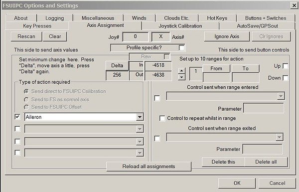
  • Navigate to the ‘Axis Assignment’ tab to open the menu to assign the flight controls to FSUIPC for direct calibration (Figure 6).

  • Move the flight controls to the full extent of their movement.  For example, turn the yoke left and right or push/pull the control column forward and aft to the end of their travel.  You will observe that FSUIPC registers the movement and shows this movement by a series of numbers that increase and decrease as you move the flight controls.  It will also allocate an axis letter.

  • At the left side of the menu (Figure 6) is a label ‘Type of Action Required’; ensure ‘Send Direct to FSUIPC Calibration’ is checked (ticked).  Open the display menu box directly beneath this and select/highlight the flight control functionality (ailerons, elevator or rudder pedals).  Check (tick) the box beside the function.


FIGURE 5:  FSUPIC Main Menu


FIGURE 6:  FSUIPC Axis Assignments


Calibrating Flight Controls Using FSUIPC

  • Select the Joystick Calibration’ tab.  This will open an 11 page menu in which you calibrate the flight controls in addition to other controls, such as multi-engine throttles, steering tiller, etc.  Select page 1/11 'main flight controls' (Figure 7)

  • Open the ‘Aileron, Elevator and Rudder Pedals’ tab (1 of 11 main flight controls).  Note beside the function name there are three boxes labelled ‘set’ that correspond to min, centre and max.  There is also a box labelled ‘rev’ (reverse) which can be checked (ticked) to reverse the directional movement of the axis should this be necessary.  The tab labelled ‘reset’ located immediately below the function name opens the calibration tool.  The ‘profile specific’ box is checked (ticked) when you want the calibration to only be for a specific aircraft; otherwise, the calibration will be for all aircraft (global).  The box labelled filter is used to remove spurious inputs if they are noted and for the most part should be left unchecked (not ticked).  The tab labelled ‘slope’ will be discussed shortly.

  • Click the ‘reset’ tab for the ailerons and open the calibration tool.  Move the yoke to the left hand down position to its furthest point of travel and click ‘set’ beneath max.  Release the yoke and allow it to center.  Next, move the yoke to the right hand down position to its furthest point of travel and click ‘set’ beneath min.  Release the yoke and allow it to center.  If a null zone is not required, click the ‘set’ beneath centre.

If a problem occurs during the calibration, the software will beep indicating the need to restart the calibration process.  The basic calibration of the yoke is now complete.  However, to achieve greater accuracy and finesse it is recommended to use null zones and slope functionality.


FIGURE 7:  FSUIPC Joystick Calibration (ailerons, elevator and rudder)


Null Zones

The null zone concept has been discussed earlier in this article.

If a null zone is required either side of the yoke center position, move the yoke to the left a short distance (1 cm works well) and click ‘set’ beneath centre.  Next, move the yoke 1 cm to the right and click ‘set’ beneath centre.  

As you move the yoke you will observe in the side box a series of numbers that increase and decrease; these numbers represent the movement of the potentiometer.  It is not important to understand the meaning of the numbers, or to match them.

Replicate the same procedure to calibrate the elevators and rudder pedals (and any other controller devices)

To save the setting to the FSUIPC.ini file click ‘OK’

It is a good idea to save the FSUIPC.ini file as if a problem occurs at a later date, the calibration file can easily be resurrected.  The FSUIPC.ini file is located in the modules folder that resides in the FSX or Prepar3D route folder.  

Slope Functionality

Slope functionality is identical to the sensitivity setting in FSX and Prepar3D.  Decreasing the slope (negative number) causes the controls to be more sensitive when moved, while a positive number reduces the sensitivity. To open the slope calibration, click the ‘slope’ tab.  This will open a display box with an angled line.  Manipulating the shape of this line will increase or decrease the sensitivity.

Slope functionality, like the null zone requires some experimentation to determine what setting is best.  Different flight controls have differing manufacturing variables, and manipulating the slope and null zone allows each unit to be finely tuned to specific user preferences.

Does FSUIPC make a Difference to the Accuracy of the Calibration ?

In a nutshell – yes.  Whilst the direct assignment and calibration in FSX and Prepar3D is good, it's only rudimentary.  FSUIPC enables the flight controls to be more finely adjusted equating to a more stable and predictable response to how the controls react.

Potential Problems

If using FSUIPC for axis assignment and calibration, remember to uncheck (not tick) the ‘enable controller’ box and delete the axis assignments in FSX or Prepar3D – only one program can calibrate and control the flight controls at any one time.  If calibration from both FSX or Prerpar3D and FSUIPC are used at the same time, spurious results will occur when the flight controls are used.

If the calibration accuracy of the flight controls is in doubt (spurious results), it is possible that the simulator software has inadvertently reassigned the axis assignments and enabled calibration.  

There's an intermittent issue in FSX and Prepar3D where the software occasionally enables the controllers and reassigns the axis assignment, despite these settings having been unchecked (not enabled).  If a problem presents itself, it's best to double check that this has not occurred.  This is why I recommend that the settings be deleted, rather than just being unchecked.

Final Call

Many enthusiasts are quick to blame the hardware, avionics suite, or aircraft package, when they find difficulty in being able to control the flight dynamics of their chosen aircraft.  More often than not, the problem has nothing to do with the software or hardware used, but more to do with the calibration of the hardware device.

The above steps demonstrate the basics of how to calibrate the flight controls - in particular the ailerons.  If care is taken and you are precise when it comes to fine-tuning the calibration, you maybe surprised that you are now able to control that 'unwanted pitch' during final approach.

Further Information and Reading

Documents relating to FSUIPC can be found in the modules folder in your root director of flight simulator on your computer.  The below link addresses how to calibrate the steering tiller.