B737-500 Throttle Conversion to NG Style - Overview

This is the second throttle unit I’ve owned and based on experience, there are many changes that have been implemented that are different to the earlier unit.

The throttle quadrant is a relatively complicated piece of kit.  To do it justice, rather than write about everything in one very long post, I’ve decided to divide the posts into sections.  

This is the first post that will deal with the general attributes of the throttle unit, interface cards used and touch on the automation and motorization of the unit.  Further detailed posts will address individual functionality, conversion and troubleshooting.

Historical Perspective and Conversion

The throttle quadrant and center pedestal were removed from an Alaskan Air Boeing 737-500 airframe.  I purchased the unit directly from the teardown yard in Arizona (via a finder).  

The conversion to full automation and motorization was not done by myself, but by a good friend of mine who is well versed in the intricacies of the B737 and in the various methods used to install automation to a throttle unit.  I am very fortunate to be friends with this individual as in addition to being an excellent craftsman with a though understanding of electronics; he is also a retired Boeing 737 Training Captain.

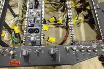
forward bulkhead of oem 737-500 throttle

New Design

The new throttle unit has been converted to Flight Simulator use based on a new design.  The interface cards, rather than being mounted on the forward bulkhead have been mounted within the Interface Master Module (IMM) which is separate to the actual throttle unit.  The DC motors required for throttle and speed brake motorization are mounted forward of the throttle unit (in the traditional location).  

Connection from the throttle to the IMM is via specially-adapted VGA cables and D-Sub plugs.  This keeps the unit clean of unsightly wiring and interface cards.  it also keeps loose cables and wires to a bare minimum on the outside of, and inside the unit; automation and motorization means that there are now moving parts and it’s important to separate delicate cards and wiring away from mechanically moving parts

This is in stark contrast to my first throttle that had the interface cards mounted directly on the forward bulkhead and within the unit.

In addition, micro buttons have been used in some circumstances to counter the traditional method of using potentiometers to control calibration of the speed brake, flaps and throttles.

Components - Interface Cards and Motors

Conversion of any OEM part to operate within Flight Simulator requires interface cards.  The following cards are used to convert analogue outputs to digital inputs for the throttle unit.  The cards also provide functionality for the fire panel, landing gear, yaw dampener, flaps and brake pressure gauges on the Main Instrument Panel (MIP).  All cards are mounted on the separate Interface Master Module (IMM).

  • Alpha Quadrant Motor Controller card A - TQ automation & logic CMD A channel

  • Alpha Quadrant Motor Controller card B - TQ automation & logic CMD B channel

  • Phidget High Current AC Motor Controller card – Provides two channels for trim wheel speeds and trim wheel movement

  • Phidget Motor Controller Advanced Servo card – Provides the interface or bridging between the Alpha Quadrant cards and flight avionics and CMD A

  • Phidget Motor Controller Advanced Servo card - Provides the interface or bridging between the Alpha Quadrant cards and flight avionics and CMD B

  • Phidget Motor Controller Advanced Servo card – Movement of flaps gauge

  • Phidget Motor Controller Advanced Servo card – Movement of trim tab indicators

  • Leo Bodnar BU0836 A Joystick Controller card – Controls all switches & buttons on TQ

  • PoKeys 55 card - Flaps (buttons)

  • Phidget 0/0/8 relay card – Speed brake, auto throttle relays CMD B, fire panels, trim wheel revolution speed on CMD B

  • Belkin 7 input USB 6.5 amp powered mini hub (2) – TQ

  • 2 two-stage DC pump motors - Powers the movement of the trim wheels, trim tab indicators

  • 2 electric motor - powers the movement of the speedbrake lever and thrust levers

Phidget Cards

Phidgets cards provide the necessary interface between the throttle and flight simulator.  I believe that Phidget cards are probably one of the more reliable cards on the market that can be used to directly interface OEM parts to flight simulator.

In addition to the two Alpha Quadrant cards mentioned above, a Phidget High Current AC Controller card acts as a ‘bridge’ to allow communication between the Alpha Quadrant cards and the avionics suite (in this case ProSim737).  This card also provides the connectivity to allow the trim wheels to spin when CMD A or B is selected on the Main Control Panel (MCP).

Trim Tab Indicators and Throttle Buttons

To control the movement of the two trim tab indicators, a Phidget Motor Controller Advanced Servo card is used to control the output to two, two-stage DC motors.  These motors, which are normally used to power water pumps, control the variable speed of the trim indicators and the revolution of the trim wheels.  The speed which the indicator moves is reliant on the user setting within the “trim section” in the configuration page of the flight avionics software.

A Leo Bodnar BU0836A Joystick Controller card is used to control all switches and buttons on the throttle unit, while a Phidget 0/0/8 relay card is used to turn logic on and off that controls the actions of the speed brake.  

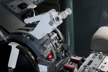
white colour of next generation thrust levers is unmistakable

Automation

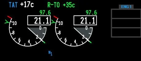
Essentially, automation is the use of CMD A or CMD B (auto pilot) to control the N1 outputs of the throttle, and motorization is the moving of the throttle levers in unison with N1 output.  

Automation is achieved by the use of two main motor controller cards (Alpha Quadrant cards); one for CMD A and another card for CMD B.   Each card operates separately to each other and is dependent upon whether you have CMD A or CMD B selected on the Main Control Panel (MCP).

The Alpha Quadrant cards provide the logic from which the automation of the throttle unit operates.  

Being able to program each card allows replication of real aircraft logic and systems.  Whenever possible, these systems and their logic have been faithfully reproduced..

Main Controller Cards (thanks NASA)

The controller card I have used is not a Phidget card but a specialist card often used in robotics (Alpha Quadrant card).  The software to program the card has been independently developed by a software engineer and does not utilize Phidgets.

The technology used in the controller card is very similar to that utilized by NASA to control their robotic landers used in the space industry.  The technology is also used to control robots used in the car industry and in other mass production streams.  One of the benefits of the card is that it utilizes a software chip that can be easily replaced, upgraded or changed.  

cp flight mcp

CMD A/B Auto Pilot - Two Independent Systems

Most throttle units only use one motor controller card which controls either CMD A or CMD B; whichever auto pilot you select is controlled by the same card.  

In the real aircraft to provide for redundancy, each auto pilot system is separate.  This redundancy has been duplicated by using two Alpha Quadrant controller cards, rather than a single card.  Each controller card has been independently programmed and wired to operate on a separate system.  Therefore, although only one CMD is operational at any one time, a completely separate second system is available if CMD is selected.

Synchronized or Independent Motorization

Synchronization refers to whether the two throttle thrust levers, based upon separate engine N1 outputs, move in unison with each other (together) or move independently.

In the real aircraft, on earlier airframes, the levers were synchronized; however, the NG has a computer-operated fuel control system which can minutely adjust the N1 of each engine.  This fuel management can be observed in a real aircraft whereby each throttle lever creeps forward or aft independent of the other lever.

Programming flight simulator to read separate N1 outputs for each engine and then extrapolating the data to allow two motors to move the throttle levers independently is possible; however, the outputs are often inaccurate.  This inaccuracy can be seen on reproduction throttle units that show huge gap between lever one and lever two when automating N1 outputs.  

I decided to maintain the older system and have both levers synchronized.  If at some stage in the future I wish to change this, then it’s a matter of adding another motor to the front of the throttle bulkhead to power the second thrust lever.

Although the TQ is automated, manual override (moving the thrust levers by hand) is possible at any time as long as the override is within the constraints of the real aircraft logic and that provided by the flight avionics (ProSim737).

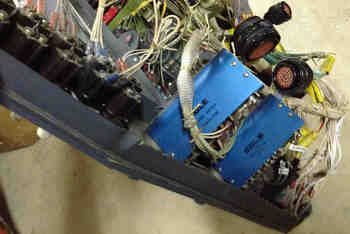
electric motors provide the power to move the thrust levers and speedbrake lever

Motors

Four motors are used in the throttle unit.

Two electric motors are mounted forward of the bulkhead.  These motors power the movement of the throttle levers and speed brake.  Two DC pump motors are installed directly within the throttle unit and power the movement of the trim wheels and trim tab indicators.

A clutch system is also mounted to a solidly mounted frame on the forward bulkhead.  The clutch system is used by the speed brake.  The method of locomotion between clutch and thrust levers is a standard automobile style fan belt.  

To allow both thrust levers to move in unison, a bar linking the lever which is motorized to the non-motorized lever was fabricated and attached to the main shaft of the motor.  

The motors chosen were automobile electric window motors.  These motors are powerful, provide excellent torque and were selected due to their reliability and ease of use.

flight simulator using oem throttle

Trim Wheel Spinning

The trim wheels can spin at two different speeds dependent upon whether the auto pilot is engaged or whether automation is turned off (manual flying).  A Phidget High Current AC Controller card is used to interface the spinning of the trim wheels.  The Phidget card has two channels and each channel can be programmed to a different revolution speed.  The speed of the revolutions is controlled directly within the Phidget Advanced menu within the ProSim737 software.   

The system was duplicated using a second Phidget card to ensure that both CMD A and CMD B operated identically.

In the real aircraft there are four different revolution speeds dependent upon the level of automation and the radio altitude above the ground.  Although it is possible to program this logic into the Alpha Quadrant cards and bypass ProSim737 software, it was decided not to as the difference in two of the four speeds is marginal and probably unnoticeable.  Further, the level of complexity increases somewhat programming four speeds.

Trim Wheel Braking

In the real aircraft, the trim wheels have an effective braking mechanism that stops the trim wheels from spinning down; basically it’s a brake.  Testing of a military specification motor with brakes to stop wheel movement was done; however, the motors were too powerful and whilst the trim wheels did stop spinning, the noise and jolt of the brake activating was not acceptable.

Functionality and Configuration

The TQ has been converted to allow full functionality, meaning all functions operate as they do in the real Boeing aircraft. Speed brake, flaps, parking break, reverser levers, thrust levers, trim stabilizer runaway toggles, trim tab indications, TOGA and A/T buttons, horn cut out, fuel levers and two speed trim wheel spinning have been implemented.

These functions and the process of conversion and calibration (potentiometers and micro buttons) will be addressed in separate posts.

Configuration, if not directly to the Alpha Quadrant cards via an external software program is either directly through the avionics suite (ProSim737) and the Phidgets card software or through FSUIPC.  Where possible, direct calibration and assignments via FSX have not been used. 

oem 737-500 backlighting

Backlighting

The throttle unit's light plates, with the exception of the parking brake which is illuminated by a 28 Volt bulb, are back lit by 5 Volt aircraft bulbs.  A dedicated S150 5 Volt 30 amp power supply is used to supply power to the bulbs.

Stab Trim T-Locker Toggles

The only function which is different from the real aircraft is the stab trim switch.  The left hand toggle operates correctly for runaway trim; however, the right hand toggle has been configured that, if toggled to the down position, the trim wheels will stop spinning.  The toggle is a basic on/off circuit and stops current going to the motors that move the trim wheels.  

The reason for doing this is that I often fly at night and spinning trim wheels can be quite loud and annoying to non-flyers…  The toggle provides a simple and easy way to turn them on or off at the flick of a switch.

oem 737-500 t-lockesr

Finding T-Lockers

Finding T-Locker toggles that are used in the NG series airframes is not easy.  Reproduction units are available but they appear cheesy and rarely operate effectively as an OEM toggle.  Earlier airframes used metal paddles (my earlier 300 series throttle used these type of trim switches) while the 400 series uses a different style again.  Trim switches are usually removed and reinstalled into an aircraft; therefore, I was fortunate that the throttle unit I secured had the later model T-Lockers.

The switches are called T-Lockers as you must manually pull down the cover from each switch before pulling the toggle downwards.  This is a safety feature to ensure that the toggles are not inadvertently pushed by the flight crew.

Thrust Handles - Colour

The colour of the throttle quadrant between the 737 aircraft variants leading towards the Next Generation series is similar, however, the colours are slightly different on the Next Generation throttle are different.

First, the thrust levers are not painted, but are cast in the actual colour.  Despite this, older aircraft will exhibit UV fading causing the thrust levers to appear darker and yellower.

There is no distinct RAL colour, however, RAL 7047 is very close.  The colour of the thrust levers is identical to the side walls, knobs and liners.  The bac hex colour designation in BAC#705 (Federal STD 595B-36440).  If you do not understand the various colour definition, search google for further information.

Importantly, it is almost impossible to find the correct colour codes as Boeing guards this information carefully to ensure it is not copied by rival aircraft manufacturers (why I am not sure).

Center Pedestal - Cabling and Wiring

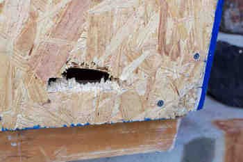
The three-bay center pedestal, mounted directly behind the throttle unit, has a number of cables and connections required for individual panel operation.  Rather than have these cables weave through the mechanism of the throttle (remember this is an automated throttle and there is considerable movement inside the unit), I’ve opened a hole into the platform directly under the pedestal.  

Any wiring or cabling is routed through this hole into a piece of round flexible conduit tubing (it’s actually the hose from a disused washing machine). The cables, after making their way to the front of the platform, then connect either to the computer or the Interface Master Module.

The use of flexible tubing is not to be underestimated as any cabling must be protected to avoid the chance of snagging on the under-floor yoke and rudder mechanisms which are continually moving.  

More Pictures (less words...)

In this post we have discussed a general overview of the throttle quadrant and examined the automation and motorization.  We also have looked at the interface cards used and studied the stab trim T-Lockers in more detail.  In future posts we will examine the different parts of the throttle unit and learn how they were converted and calibrated to operate with Flight Simulator.

Click any mage to make it larger.

  • UPDATED 16 August 2022

Handy Software to Determine Hard Drive Usage - HD Graph

Every now and again I find a program which is very handy.  We all know that flight simulator is hard drive hungry; once scenery files and other specialist files are added the hard drive can fill up very quickly.

HD Graph is a standalone program (does not need to be installed to your computer) that allows you to interrogate your hard drive to graphically display the hard disk space usage.  It shows all the directories and subdirectories of the hard drive on a single graph, allowing to see the largest directories at a glance. 

At the moment the tool is available free of charge from the HD Graph website.

OEM B737 Landing Gear Mechanism - Installed and Functioning

oem 737-800 landing gear mechanism. impossible to upgrade

I have replaced the landing gear lever supplied by Flight Deck Solutions (FDS) with the landing gear mechanism (LGM) from a Boeing 737-500 aircraft.  The reason for the replacement of the landing gear was not so much that I was unhappy with the FDS landing gear, but more in line with wanting to use OEM parts.

Before wiring further, there are a number of differing styles of landing gear mechanisms seen on Boeing aircraft depending upon the aircraft series.  For the most part, the differences are subtle and relate to wiring and connectivity between different aged airframes.  However, there is a difference in the size of the gear knob between the Boeing classics (300 through 500) and the Next Generation; the knob is the opaque knob located at the end of the gear handle.  On the classics this knob is rather large; the Next Generation has a knob roughly 20% smaller in size.  There is also a slight difference in the length of the stem - the Next Generation stem being a little shorter than the classics.

The landing gear mechanism was originally used in a United Airlines B737-300, and had the larger style knob. The knob was removed and replaced with a Next Generation knob. The stem was also shortened to the correct size of the Next Generation.

Anatomy of LGM

The landing gear mechanism is quite large, is made from aluminum and weights roughly 3 kilograms.  Most of the weight is the heavy solenoid that can be seen at the front of the unit.  A long tube-like structure provides protection for the wiring that connects the solenoid to the harness and Canon plug at the side of the unit.  The red-coloured trigger mechanism on the gear stem is spring loaded, and the landing gear lever must be extended outward (toward you) when raising and lowering the gear.

Installation and Mounting

I am using a Main Instrument Panel (MIP) designed by Flight Deck Solutions which incorporates a very handy shelf.  Determining how to mount the gear mechanism was problematic as the position of the shelf would not allow the mechanism to be mounted flush to the MIP.  After looking at several options, it was decided to cut part of the shelf away to accommodate the rear portion of the gear mechanism. 

Once this had been done (rather crudely), it became apparent that, although the mechanism mounted flush to the MIP the landing gear lever was not in the correct position; the lever was too far out from the front surface of the MIP and the trigger, when the lever was in the down position, did not sit inside the half-moon protection shields.

Spacer

The solution to this problem was to design and mount a 0.5 cm thick spacer to the front of the landing gear.  This spacer was made from plastic and cut to the exact measurement of the gap that the landing gear lever moves through.  Attaching the spacer to the lightweight aluminum of the landing gear mechanism was straightforward and was done with four small screws. 

Once the spacer was attached, the trigger of the landing gear sat in the correct position relative to the two half-moon protection shields.

Carefully removing the two ridges from the FDS main backing plate

Cutting the FDS Plate

Another minor hurdle was the aluminum plate located behind the FDS light plate had to be altered.  The FDS landing gear secures to two ridges that are at 90 degrees to the MIP.  These two ridges had to be removed to enable the flat surface of the front of the OEM landing gear mechanism to sit flush.  A Dremel was used to cut through the thin aluminum, and the two ridges were removed.

Custom Bracket

Custom bracket that is used to secure the upper part of the landing gear mechanism to the rear of the MIP

The next issue was how to attach the landing gear mechanism to the MIP.  I made a custom bracket that fitted snugly to the upper part of the gear mechanism. 

To secure the bracket to the gear mechanism, the bracket leg was positioned over two pre-existing holes and secured to the body of the mechanism by two machine screws.  To attach the mechanism to the MIP, the two holes in the bracket were aligned with two existing holes in the MIP and secured by machine screws and nuts. 

To secure the lower part of the landing gear mechanism to the MIP, I replaced the existing bolts used to attach the half-moon protection shields to the MIP, with longer bolts.  I then drilled two small holes in the front plate of the landing gear mechanism and spot welded a nut to the inside of each hole.  The bolts could then be used to secure the gear mechanism to the MIP.  To stop lateral movement of the gear mechanism, I used a standard L bracket to secure the unit to the shelf of the MIP.

The reason for the secure mounting will become obvious later in the post.

Stem Length and Initial Configuration

One aspect to take note is that the Next Generation landing gear lever is one inch shorter than the classics; therefore, one inch of the lever needs to be removed. This involved removing the stem, cutting off one inch, and painting the cut portion with black paint. The stem was cut with an angle grinder

Two buttons were used to enable the three positions of the landing gear (up, center and down) to be calibrated. The center position does not require a button. The two buttons (not pictured) are located inside the unit screwed to the inner side of the housing. The buttons are triggered when the stem of the landing gear passes over them.

landing gear solenoid.  The LGM does have a handy foot beneath the solenoid for attachment to the MIP shelf; however, this foot sits too far forward of the shelf to be of use when the LGM is flush to the MIP. it was designed for an oem mip

Reproduction or OEM

There are three primary reasons for using an OEM landing gear mechanism rather than a reproduction unit.

The mechanism, as mentioned earlier, includes a solenoid.  This solenoid stops the landing gear from being raised or lowered at certain landing gear lever positions.  Reproduction units rely on software to replicate the function of the solenoid.  Using an OEM unit allows the solenoid to be used.

Another difference is the trigger.  Because reproduction units do not use a solenoid, a spring-loaded trigger is not required. An OEM LGM requires a spring-loaded trigger to engage or disengage the solenoid.

Furthermore, reproduction units often do not provide correct positioning of the trigger in relation to the half-moon protection shields.  The half-moon and trigger are safety features, and the trigger should be partially hidden between each of the two half-moons when the landing gear is in the DOWN position.

Canon plug on ABS plastic mounting plate.  The use of the Canon plug enables a cleaner wiring configuration. it also facilitates easier removal of the mechanism if necessary

Interfacing

To enable the solenoid to be used, a Phidget 0/0/8 relay card was used.   The card interfaces the actions of the solenoid (on/off) and is then read by the avionics suite (ProSim737). 

The Phidget card is mounted in the System Interface Module (SIM) and connection from the card to the landing gear mechanism is via the Canon plug. 

To enable the Canon plug to be used, the pin-outs were determined using a multimeter in continuity mode. The solenoid requires 28 volts to enable activation, and the power connects directly to the Canon plug from a Meanwell 28 volt power supply.

Muscle Required!

To use OEM landing gear requires muscle!  Pulling the gear lever from its recess position is not a slight pull.  Likewise, moving the gear lever between down, off and up requires a bit of strength.  This is why mounting the mechanism securely is very important.

Operation and Safety Features

Boeing has incorporated several devices in the aircraft, such as squat switches, computerized probes and mechanical locks (down and up-locks) to ensure that the landing gear cannot be raised when there is weight on the main landing gear.  If weight is registered, then the landing gear lever lock is activated inhibiting the gear lever from being able to be placed in the UP position.  This lock is controlled by the solenoid.   

An override trigger in the lever may be used to bypass the landing gear lever lock.  Depressing the trigger will disengage the lock and allow the gear lever to be moved to the UP position.  The reason for the half-moons should now be obvious.  By partially covering the trigger, the half-moons act as a physical barrier to stop a pilot from easily accessing the trigger mechanism to disengage the landing gear lever lock.

After rotation, the air/ground system energizes the solenoid which opens the landing gear lever lock allowing the gear lever to be raised from the DOWN to the UP position.

Scratching to the gear lever shaft.  Note the access pin on the shaft that allows removal of the retractable trigger.  Also note the smaller NG style knob which replaced the larger knob used on the classics

How it Works in the Real Aircraft (Hydraulic Pressure)

In the real Boeing aircraft, hydraulic pressure is used to raise the landing gear.  This pressure is supplied through the landing gear transfer unit.  

Hydraulic system B supplies the volume of hydraulic fluid required to raise the gear.  Conversely, hydraulic system A, by supplying pressure to release the up-locks, is used to lower the landing gear.  Once the up-locks have been disengaged, the gear will extend by gravity, the air load, and to a limited extend hydraulic pressure.  

Moving the landing gear lever to OFF (following take off) will remove all hydraulic pressure from the system.

Lineage

Originally the landing gear mechanism was used in United Airlines N326U. Unfortunately, due to copyright, an image cannot be posted.

In-Flight Testing

The solenoid and trigger mechanism operate in the simulator as it does in the real aircraft.  When you start flight simulator and ProSim737 there is an audible clunk as the solenoid receives power.   Immediately after rotation, you hear another audible clunk as the solenoid is energized (to open the landing gear lock).

If you want to raise the gear lever to UP whilst on the ground, the only way to do so if by depressing the trigger to override the landing gear lock.

Hydraulic pressure is not simulated.

Final Call

Is the effort of installing an OEM landing gear mechanism to the simulator worthwhile?  I believe the answer is yes. The use of the solenoid provides added realism as does the use of a spring-activated trigger. Furthermore, the effort that is required to extend and move the landing gear lever in stark contrast to the effort required when using a reproduction unit.

Acronyms

OEM - Original Equipment Manufacture

FDS - Flight Deck Solutions

MIP - Main Instrument Panel

LGM - Landing Gear Mechanism

NG - Next Generation (B737-800NG)

Half-moons - the two protection plates that are positioned either side of the trigger of the landing gear when in the landing gear is in the DOWN position

Full-time Construction - Light at the end of the Tunnel

Revealed after removing the lid of the crate - an OEM NG style throttle unit.   The three bay center pedestal was packed to the gunnels with OEM parts!

It's been three weeks since my oversized box arrived from the United States and the time has not been spent idle. 

The first morning was spent attempting to drag, carry and push a rather large and heavy (110 kilos) crate from the side garden, up five sets of cement stairs, through the door and then into the flight simulator room. 

The only way one person could move the crate was to unpack whatever was possible into the garden, then construct a  pulley system to drag the crate and its remaining contents up the stairs.  The crate then had to be pushed along the carpet, using cardboard as a slide (to protect the carpet).  It was a relief to note that the crate had a few centimeters clearance between the sides of the crate and the door edges! 

This worked out well, although it took most of the morning, as unpacking the throttle unit outside the simulator room and  moving it to the room would have been problematic.

Fork Lift Damage

My concerns about fork lifts and delicate cargo came to fruition.  A fork lift had rammed one side of the crate leaving the tell-tale evidence - a fork shaped hole!  Fortunately, most of the delicate items were not damaged and for the most part the fork only pushed air.  A book that was included in the crate received much of the brunt and saved the fork from travelling further.  But, so much for my book which now has a hole in it....

Construction Mode

I've been in construction mode attempting to get as much done before I return to my job.  The days have been long and the wire clippers are becoming blunt from endless use!  Many hours have been spent thinking how to do things and then implementing decisions - some successful and others requiring a re-think.  The telephone has been "running hot" as I discuss options with my friend (who also has a B737 simulator) on the best methods to use.

There has been  challenges both in construction and in software development; however, after almost three solid weeks, the light can now be seen at the end of the tunnel.  Hopefully, I'll have some time spare soon to collate some photographs  with words and make a few detailed posts.

Wiring the Simulator - Aviation Wire

aircraft wire by the roll

When I first began to work on my simulator, I used whatever wire was available; usually this was automotive electrical wire.  The wire was inexpensive and seemed to do the job; however, there were several shortcomings.  

To carry the appropriate amperage the wire selected was quite large in thickness; therefore, quite inflexible.  This inflexibility resulted in the wire coming loose at connections quite easily.  The thickness also made routing numerous wires quite challenging and at one stage, my simulator looked like a rat’s nest of snaking coloured wires.

After a few connection issues, I began to rethink my approach.  

I have since replaced the automotive wiring with a wire grade more suitable for the purpose.  The wire I use is aviation wire which is available in various gauges (thicknesses) and colour options.  The benefits in using this wire are it:

  • Withstands physical abuse during and after installation 

  • Has a good high and low temperature properties  

  • Is very flexible and small enough to be run in tight places

  • Can be obtained in varying gauges and colours

  • Has a high flex life  

  • Has good out-gassing characteristics

  • Has a fair cold flow property (probably not that important as the simulator is not going to altitude)

The wire can easily be obtained in rolls from supply chain stores or from e-bay.  Enter the following wire reference code into either e-bay or google:  Part Number: 22759-16-22-9; 22 AWG WHITE TEFZEL WIRE.

Please note, this is the wire I use (and many other builders).  There is a wide variety of wire available in the market that is suitable for building, so don't become overly concerned if you've already used a different type of wire.  The main point to remember is that wire is rated to the application and voltages your intending to use.  The wire mentioned is ideal for all wiring requirements of the simulator with the exception of very high voltage requirements.  High voltage requires a wire of lower gauge (thicker wire) to ensure minimal voltage drop over distance. 

The same type of wire as mentioned above can be purchased in differing gauges (thicknesses).  I find 22 gauge is a good overall gauge to use.  Remember that voltage (amps) is rarely being applied to the wire continuously (exception is from power supplies).

jr servo wire security clips

Easy Connect/Disconnect Connectors

Often there is a need to connect a piece of wire to another piece of wire or part and have the ability to be able to disconnect the wires easily and quickly.  For example, often panels must be removed from the center pedestal; having the ability to disconnect wires easily allows complete removal of the item without destroying the attachment wires!

There are dozens of connectors available for joining or extending wires – some are better than others.

I use (where possible and when voltage/amp requirements dictate) JR servo wire security clips.  These little clips allow three wires to enter to either side of the connection, are made from heavy duty plastic, and have a guaranteed clipping mechanism that will not unplug itself.  Search the Internet for JR extension servo clips. 

For applications requiring more than three wires, or higher voltage/amps, I use a high quality terminal block, Canon style plug or a D-Sub plug.  The later two requiring each wire to be very carefully soldered into the appropriate wire reciprocal in the plug.  I also use Mylar quick release plugs for some applications.

All other wires that require a permanent connection are usually soldered together with wire shrink wrap.  Soldering always provides the best connection.

Freight Dispatched - Throttle Quadrant Australia Bound

A300-600 FedEx. Flaps2approach freight was dispatched on this aircraft (Maarten Visser from Capelle aan den IJssel, Nederland, N725FD A300-600 Fedex (4542200103), CC BY-SA 2.0)

It’s taken considerable time with frequent delays since I sold my earlier B737-300 series throttle quadrant, in October 2012, to make way for a replacement 600 series TQ with three-bay pedestal.

LEFT: FedEx. Copyright Bob Wood, Airplane Pictures.Net

As I expected, “scope creep” reared its head and the original requirements changed considerably over time.  It’s almost like leaving the house to buy a second hand car and coming back with a brand new jeep with all the accessories.

Use a Freight Forwarder

Freighting something as heavy and as large as a TQ, from the United States to Australia is not without cost and I’m fortunate to be in good stead with a competent Australian freight forwarder. 

A freight forwarder's job is to look after the logistics of getting the freight from point A to point B as expeditiously as possible.  Forwarders also complete all the required paperwork that is requested by customs authorities in both the country of export and import.  A good forwarder will do everything, albeit at a cost to you; however, the fee they charge is often worth the expense, as completing the required paperwork can be very difficult and if not correctly done will result in delays and storage charges.

Often a freight forwarder will sub contract his equivalent in the country of export to look after the exporting aspects of the freight.  A forwarder has access to any number of airlines and attempts to secure a freight rate that is acceptable to the client. 

Freight rates behave like shares on the stock market, and prices fluctuate widely depending upon the price of fuel, whether the freight can be back-logged (added to a pre-paid shipment belonging to someone else) or is dispatched stand alone.

How the Freight Industry Works

The way it works is quite simple – the freighter will charge you based on the cubic surface area or weight ($$$ / kilogram) of the crate.  The amount you pay is whichever is greater!  To this there are other charges added such as: airport fees, security fees, customs clearance fees, tax, import duties, airline handling fees, terminal fees, cargo automation fees, export clearance charges and a truck tail-lift pick-up fee.  This is above the actual cost per kilogram to send the freight and any domestic carriage, pick-up and storage charges.

You're probably thinking that sea freight is less expensive and you are correct; however, shipping terminal fees usually negate much of the saving, not too mention a lengthy wait time and a higher cost for insurance.

Carrier & Route Change - QANTAS then FEDEX

The freight industry is not a squeaky clean industry and under-the-carpet arrangements are commonplace.  If another carrier has space that is being sold at a cheaper rate, then your freight often will be shipped with the airline with the lesser expensive freight charge.  Unfortunately, this saving is not passed along to the customer, but equates to a higher profit for the freighter.  

The freight business have a term they use called "time sensitive", which basically translates to "we do what we want and you wait"!

For example, my freight was supposed to be freighted with QANTAS for a quick Los Angeles – Melbourne (KLAX-YMML) flight followed by a domestic service further south to Hobart (YMHB). 

However, space became available with FedEx at a cheaper rate than offered by QANTAS and the Ameriican freight forwarder made a carrier and route change.  Instead of LosAngleles to Melbourne, the crate was dispatched via a FedEx MD11 from KLAX to Honolulu (PHNL).  From here it will travel via a Fed EX 747-400 through to Sydney (YSSY) and then onto Melbourne.  From Melbourne a domestic carrier will continue the pilgrimage to Hobart…

For the consigner (me), the longer a trip takes and the more times the freight has to be unloaded, stored and reloaded into another aircraft the higher the probability of potential damage.  If your wondering what could go wrong, think about how heavy freight is moved about - they use a fork lift!

At least FedEx, like DHL and UPS are specialists in moving freight.

Large Crate - Taking Advantage of Volume

I've spent considerable time over the last 10 months or so tracking down and purchasing genuine B737 OEM parts required for the simulator.  These have been stored at my friend's house and have been packed inside the crate along with the TQ.  The crate is full to the brim of "goodies" that will keep me busy for months... 

It's good to know I've saved considerable future postage costs and reduced the global carbon footprint by being able to add things to this shipment.

Impatient Wait

It’s an impatient wait, knowing that as I write the crate of “goodies” has landed in Sydney and has been transferred to Melbourne.  The next hop is to Hobart, Tasmania.  It's a fact of life that transporting anything to Hobart (an island state) takes a inordinate amount of time, so delivery is not expected to mid next week.

It's said that waiting builds character; "I seem to wait all the time....."

Oh and if your curious, the cost to send 110 kilograms chargeable weight from the US to Australia is $1453.00 AUD total.  Whoever said that building a simulator was cheap, should be "shot on the spot"!

I'm looking forward to getting back into construction mode and posting new progress updates, explanations and photographs.


Update

on 2013-08-15 22:23 by FLAPS 2 APPROACH

The crate has arrived....  It's much bigger than I anticipated.  This is the crate at the side entrance door to the house.. 

I had to make a winch and cradle system to enable me to get the crate, which weighs 110 kilos up and over the stairs and into the house.

At last, I now can get back into the construction phase of the simulator!

Time to find my wire, drill, clippers and multimeter.  There are so many OEM parts - which do I start on first.

Scope Creep - Keeping the Enemy at Bay

The Swiss Army pocket knife.  How many tools does one want?  Where do you stop?  The knife does not have a fork or spoon (D-M Commons, Wenger EvoGrip S17, CC BY-SA 3.0)

Scope Creep is a term often used in management to define the continuous growth of a project both in expenditure and time.

This phenomenon can occur when the scope of a project is not properly defined, documented, or controlled. It is generally considered a negative occurrence, to be avoided.  This said, scope creep can add benefits to a project ultimately making the end product far better than otherwise anticipated.

Typically, the scope increase consists of either new products or new features of an already approved product design, without corresponding increases in resources, schedule, or budget. As a result, the individual risks drifting away from the original purpose and scope into unchartered territory. As the scope of a project grows, more tasks must be completed within the budget and schedule originally designed for a smaller set of tasks. Accordingly, scope creep can result in a project overrunning its original budget and schedule.

Guilty as Charged...

Am I guilty of scope creep - a resounding YES.  It can be difficult to maintain your original project scope, no matter how well defined at the onset of the project; new parts, better technology, better methods to accomplish tasks, and experience are all potential budget breakers...

Scope creep has a nasty habit of sneaking up on you unaware - a few dollars here and few dollars there, a yes to this and a yes to that, and before you know it, you are over committed and over budget.  Scope creep rarely is caused by the vendor, it is more the territory of the seller or manufacturer.  Most of us have bought a motor vehicle, and have driven the car home with the addition of a tow bar, roof rack, and high fidelity stereo system - all absolutely essential according to the car salesperson...

Although the simulator will be more feature rich, reliable and aesthetically pleasing, it's important to always keep a firm hand on what your original project lines were, and try not to stray too far from your goals.  There is always something greener on the horizon, and whilst it can be tempting to stray beyond the fence to savour the new grass, always ask yourself - is this going to improve the outcome of what I set out to do and is the extra expense worth the outcome. 

Time, or lack of

A second conundrum that simulator builders often face is time, or lack of. Everyone except the very young and the retired are impacted by time.

Remember, Rome was not built in a day and many simulators can take 3-4 years until reasonably complete. 

Whether we like it or not, the process of research, procuring parts, and construction takes an inordinate amount of time, and if left unchecked will also cost you an inordinate sum of money...

Just a few thoughts to think about.

Flight Deck Builders Toolbox - Multimeter

fluke multimeter

Depending upon how much realism you’re seeking, the construction of a flight simulator can encompass a variety of techniques including: electrical, mechanical, metal and wood-working, computer and IT skills. 

The average person, unless gifted or working in these fields, rarely has the level of expertise needed to fulfill every facet of building.  Fortunately, there are others that have travelled along the same path and assistance is often relatively easy to find from the Internet and dedicated builder forums.

One skill I was lacking was electrical.  As a youngster I had dabbled with car radios, stereos and installed numerous two way radios into cars and boats.  I can remember sparks flying here and there as I connected wires incorrectly.  The only gadget I owned then was a retro-looking screwdriver that had a handle that illuminated whenever a live wire was touched.

Although many builders opt for pre made parts that do not require wiring and soldering, there will come a time when you have to do this yourself, especially if you are using real aviation parts converted to flight simulator.

In this article, I use the terms ground, earth and common interchangeably - they all have the same meaning. The three terms originate from different countries. For example, in Australia we use the term earth, while in the United States the word ground or common is used.

The Multimeter

A multimeter is used for diagnosing problems with electrical systems and is probably the most useful tool any builder can have in his arsenal of tools.   If I’d had access to a multimeter in my earlier years, I’m sure the sparks would not have been as bright as they were and I wouldn’t have' fried' as many fuses and radio components as I did.

Most multimeters can be used to measure a number of variables, the most valuable in my opinion being the ability to measure of continuity.

Continuity Testing - numerous examples

One of the basic uses a multimeter has in flight deck building is to test for continuity.  Testing for continuity checks to see if there is an electrical connection between two points. If two points are electrically connected, they are said to be continuous and the current will flow unheeded.  

Testing for continuity has many useful purposes.

For example, you can determine which prong on a multi-prong Canon plug is being used to carry 5 Volts to power the back lighting on a real aviation gauge or panel.  Another example is checking to ensure current flow across wires from an interface card to a sim part.  

A further example is aircraft bulbs.  Often they are so small that viewing the filament to determine connectivity is next to impossible.  Grab your meter and place a probe on the outside of the bulb (the earth) and place the other probe at the power end of the bulb (positive).  If you hear the meter beep then the filament is not damaged and current can flow, however, if you don’t hear the beep, then the current is not flowing and the filament is damaged requiring a replacement bulb.  A similar test can be done with fuses.

Continuity testing can also help you test your soldered connections to see if they were soldered correctly.  A beginner who is not experienced in visually detecting problems with a soldered joint can become frustrated very easily, because a soldered joint can look like its soldered correctly but there may not be an electrical connection. Using a mulitmeter helps you find out if the soldered connection is good or not.  Similarly, the tool can also be used to determine if a correctly connected wire is broken somewhere along the wire’s strand.

How to Test for Continuity

Set your multimeter to the correct mode.  Look for the icon that looks like a sound wave or a Wi-Fi connection indicator on the meter.  If you can't find it refer to the manual you received with the multimeter.

  • Using the pencil probe (red or black wire), touch the connection you want to test.  

  • Using the other probe, touch the other end of the connection you want to test.

  • If you hear a beep or a buzz, there is an electric connection between the two points. 

  • If there is no electrical connection you will not hear a beep or a buzz and the display will give a reading of 0.

Using the probes to find which prong is ground (earth). Note the black probe is touching the outer casing (earth) whilst the red probe is being moved from prong to prong.  An audible beep from the multimeter will sound when the prong touches the prong that is used for ground..  It's important to ensure you are only touching one prong at a time, otherwise you will get an incorrect result

Example - Connecting Backlighting

Using continuity, let’s look at the example mentioned earlier: connecting power to illuminate the backlighting on an OEM gauge that uses a multi-prong canon plug.   

First, we need to determine which of the prongs from the plug carries power (positive) and which is ground (earth).  

Second, to check which prong is being used to carry power, touch one of the two probes to one of the prongs in the Canon plug.  Then, attach the other probe to a 5 v bulb. Always attach the probe to the positive end of the bulb which is the end point of the bulb (not the bulb casing).  Move the first probe from prong to prong in the Canon plug until you here a beep.  The beep indicates that this prong is the prong used to carry 5 Volts.

  1. To determine ground (earth), use the same technique, but instead of using the bulb, touch the probe against the outer casing of the Canon plug.  With the other probe move it between each of the prongs in the plug.  When you hear the beep this will indicate which prong is ground (earth).   

  2. The wires from the power supply (positive and earth) are then connected to the indicated prongs.  If connected correctly, the backlighting for the panel will illuminate.

The same can be done for switches and toggles or for almost any part.  Let's look at another example: 

Example - Connecting a Switch or Toggle

In this case we have a three-was switch often used in the overhead.  The switch can be moved to three positions and can be locked in one position.  The rear of the switch has three terminals.  before going further, it's important to realize that although a switch may have up to eight terminals, not every terminal is needed to connect to the simulator.  The reason there are often ancillary terminals is that in the real aircraft, a switch may also connect to other devices that a simulator does not need (such a centralized computer).

To determine which switch position correlates to the actual turning on or off of the function we need to:

  1. Place the black probe on the earth or common terminal.

  2. Place the red probe on another terminal (alligator clips are handy you secure the probe to the terminal).

  3. Move the switch toggle up and down until you hear the multimeter beep.  The beep signifies that power can travel through the circuit.

  4. Remember the position of the switch and the terminal used.

  5. Repeat the process with all terminals and double check results to ensure accuracy.

  6. Once the terminals (or pin-outs are known) connect the nominated wires from the interface card and programme whatever functionality is required in the  flight avionics software.

Other Functions and Uses

Testing for continuity is but one operation of a mulitmeter, and depending upon the type and quality of the tool, there will be other functions available, such as being able to measure current, resistance and voltage.  The last function is very handy to flight deck builders as often we use multiple voltages ranging from 3, 5, 12 and 28 Volts.  By turning the dial to the appropriate voltage selection, one probe is used to touch one side of the wire and the other probe the device.  This will determine what voltage current is travelling through the wire to/from an interface card.

Measuring current (amperage) is equally important, and to determine current flow between points, the probes are connected to each side of the device to be measured (after the red probe is placed into the AMP socket of the multimeter).  With the probes effectively interrupting the current flow, the meter is 'in-line' and any current travelling between the components will be able to be measured and displayed by the meter in amps.  

To measure the amerage, a multimeter must have an AMP function. 

There you have it, the very basics of a multimeter and why it’s important to have one in your toolbox.

Thankfully, I’ve not had any sparks or melted wires building the simulator and it’s primarily because I always use a multimeter to check any work I’ve done before turning the power on.  

I still have a retro flashing screwdriver, but it’s more a keepsake than an operational tool.

To read a sister post, navigate to: Using Interface Cards and Canon Plugs to Convert OEM 737 Parts.

Below; Multimeter explanation and demonstration (courtesy of Afro-tech-mods (U-Tube creative commons license).


Take Off / Go Around (TOGA) - Explained

Performing Go-Around can be a confusing procedure, made more so by the effects of inclement weather. 

TO/GA is an acronym for Take Off / Go Around.  TO/GA is used whenever an approach becomes unstable or environmental conditions alter that do not allow an approach and landing within the constraints that the aircraft is certified.  If you watch the short video (embedded from U-Tube) you will note that the crew utilized TO/GA when a rain squall reduced visibility to almost zero as the aircraft was about to cross the runway threshold.


VIDEO: Boeing Business Jet (BBJ)  - Final Approach engaged TO/GA due to inclement weather (courtesy & copyright "DougLesso" U-Tube).

So why is TO/GA confusing?  It’s not the actual use of TO/GA that is confusing, but more the level of automation you have in use at the time of engaging TO/GA.  By automation, I am referring to  the command mode selected for the approach: VNAV, LNAV, V/S, ILS and whether the autopilot is enaged or not (CMD A/B).  In this post three three distinct scenarios will be discussed; however, engine out (single engine) procedures will not be examined.

Scenario One

Autopilot Flight Director System (AFDS) configured for autoland:  CMD A & B engaged with localizer and glideslope captured and 'FLARE armed' and annunciated on the Flight Mode annunciator (FMA).  Auto throttle engaged.

  • Pushing the TOGA buttons will engage the Take Off / Go Around mode & Flight Director guidance will 'come alive';

  • The auto throttle will automatically move forward to produce reduced go around (RGA) thrust;

  • The Thrust Mode Display (TMD) will annunciate TO/GA and the required thrust will be displayed;

  • The autopilot will remain engaged and will pitch upwards to follow the Flight Director (FD) guidance

  • Landing gear will need to be raised and flaps retracted on schedule; and,

  • A 'bug up' will be observed on the speed tape of the Primary Flight Director (PFD) which indicates flap retraction speeds.

Scenario Two

Autopilot Flight Director System (AFDS) configured for manual landing (autopilot on):  CMD A or B engaged.  Auto throttle engaged.

  • Pushing TO/GA buttons will engage the Take Off / Go Around mode & Flight Director Guidance will 'come alive';

  • The auto throttle will automatically move forward to produce reduced go-around thrust.  However, the autopilot will disconnect;

  • The Thrust Mode Display (TMD) will annunciate TO/GA and the required thrust will be displayed;

  • The crew will need to take control and manually fly to follow the Flight Director guidance (around 15 Degrees nose up);

  •  Landing gear will need to be raised and flaps retracted on schedule; and,

  •  A 'bug up' will be observed on the speed tape of the Primary Flight Director (PFD) which indicates flap retraction speeds.

Scenario Three

Autopilot Flight Director System (AFDS) configured for manual landing (autopilot off):  CMD A or B not engaged.  Auto throttle engaged/not engaged.

  • Pushing TO/GA buttons will engage the Take Off / Go Around mode and Flight Director guidance will 'come alive';

  • The crew will need to take control and manually fly to follow the Flight Director guidance (around 15 Degrees nose up);

  • The auto throttle will not command reduced go around thrust.  The crew must manually move the throttle levers to roughly 85% N1;

  • Landing gear will need to be raised and flaps retracted on schedule; and,

  • A 'bug up' will be observed on the speed tape of the Primary Flight Director (PFD) which indicates flap retraction speeds.

The black TOGA buttons are prominent on each of the thrust levers. OEM 737-800 throttle quadrant

How is TO/GA Engaged

The Boeing 737 has two buttons on the throttle quadrant for engaging TO/GA.  These buttons are located on each thrust handle below the knob of the thrust levers.  The TO/GA buttons are not the buttons located at the end of each throttle knob; these buttons are the auto throttles (A/T) disconnect buttons.

Pushing one or two of the TO/GA buttons will engage the go-around mode and command Flight Director guidance for attitude pitch.

Depending on the level of automation set, but assuming minimal automation, the pilot-flying may need to push the throttle levers forward to roughly 85% N1 (Reduced Go Around Thrust).  Boeing pilots often refer to this technique as the 'Boeing arm' as an outstretched arm grasping the throttle levers moves the levers to 'around' 85% N1.

fma displays for toga

If the crew pushes the TO/GA button once, reduced go-around power is annunciated on the Thrust Mode Display (above the N1 indications on the EICAS screen) and also in the Flight Mode Annunciator (FMA).  Reduced go-around thrust is roughly 10% below the green coloured reference curser on the N1 indicator.  This thrust setting will generate a rate of climb between 1000 and 2000 fpm.

Flight Mode Annunciator (FMA) on Primary Flight Display (PFD) indicated TOGA and TOGA will be displayed on Thrust Mode Display (TMD).  Replace CRZ (1) with TO/GA

If the TO/GA buttons are pressed again (two button pushes), go-around thrust will be set to maximum thrust (at the reference curser). Engaging the TO/GA button twice is normally only used if terrain separation is doubtful.

A Typical Go Around (CAT 1 Conditions)

The pilot flying focuses on the instruments as the aircraft descends to about 200 feet AGL.  The pilot not flying splits his attention between his responsibilities to both monitor the progress of the approach, and identify visual cues like the approach lighting system.   If the approach lights of the runway come into view by 200 feet, the monitoring pilot will announce 'continue' and the flying pilot will stay on instruments and descend to 100 feet above the runway.

If the non-flying pilot does not identify the runway lights or runway threshold by 200 feet AGL, then he will command 'Go Around Flaps 15'.  The pilot flying will then initiate the Go Around procedure.

The pilot flying will engage the TOGA command by depressing the TO/GA buttons once, resulting in the Flight Director commanding the necessary pitch attitude to follow (failing this the pitch is roughly 15 Degrees nose up).  The auto throttle (depending on level of automation selected) will be commanded to increase thrust to the engines to attain and manage a 1,000 foot per minute climb; a second press of the TOGA buttons will initiate full thrust.  

The pilot not-flying will, when positive rate is assured, raise the landing gear announcing 'gear up all green' and begin to retract the flaps following the 'bug' up schedule as indicated on the Primary Flight Display (PFD).  Once the Go Around is complete, the Go Around Checklist will be completed.   

Important Points to Remember when using TOGA

  • If the Flight Directors (FD) are turned off; activating TO/GA will cause them to 'come alive' and provide go around guidance.  

  • Engaging TOGA provides guidance for the flight modes and/or N1 setting commanded by the auto throttle, It will not take control of the aircraft.  If the autopilot and auto throttle is engaged then they will follow that guidance; however, if the autopilot is not engaged the crew will need to fly the aircraft.

  • TOGA will not engage the auto throttle unless the autopilot is engaged.  The only way to engage auto throttle is with your hand (flip the switch on the MCP).  See sidenote below.

  • TOGA will engage only if the aircraft is below 2000 RA (radio altitude).

  • TOGA will engage only if flaps are extended.

  • Remember to dial the missed approach altitude into the Mode Control Panel (MCP) after reaching the Final Approach Fix (FAF). The FAF is designated on the approach plate by the Maltese cross.  This ensures that, should TOGA be required, the missed approach altitude will be set.

Side-note:  It is possible to engage the auto throttle using the TO/GA buttons if the auto throttle is in ARMED mode and the speed deselected on the MCP.  Note this method of auto throttle use is not recommended by Boeing.

Flight Crew Psychology

Flight crews are as human as the passengers they are carrying, but it’s difficult to accept that a Go Around is not a failure, but a procedure established to ensure added in-flight safety.  Several years ago airline management touted that a go-around required a detailed explanation to management; after all, a go-around consumes extra fuel and causes an obvious delay as the aircraft circles for a second landing attempt. This philosophy resulted in several fateful air crashes as flight crews were under time and management pressure to not attempt a go-around but continue with a landing.

Management today see the wisdom in the go-around and many airlines have a no fault go-around policy.  This policy is designed to remove any pressure to land in unsafe conditions - regardless of the reason: visibility, runway condition, crosswind limits, etc.  If one of the pilots elects to go-around, that decision will never be questioned by management.  So while TO/GA isn't the desired landing outcome, a go-around is not considered a failure in airmanship.

Minimal Discussion

This post has briefly touched on the use of TO/GA in an approach and landing scenario; nonetheless, to ensure a more thorough understanding, I urge you to read the Flight Crew Operations Manual (FCOM) available for download in the Training and Documents section of this website. 

Acronyms Used

  • AFDS - Autopilot Flight Director System

  • A/T - Auto Throttle Category 1 - Decision height of 200 feet AGL and a visibility of 1/2 SM

  • CMD - Command A or B (autopilot)

  • FAF – Final Approach Fix

  • FD - Flight Directors

  • FMA - Flight Mode Annunciator

  • FPM - Feet Per Minute

  • MCP - Mode Control Panel

  • N1 - Commanded Thrust % (rotational speed of low pressure spool)

  • RA - Radio Altimeter

  • RGA – Reduced Go-Around Thrust

  • TMD - Thrust Mode Display (on EICAS display)

  • TO/GA - Take Off / Go Around. Written either as TO/GA or TOGA

Avoiding Confusion: Acceleration Height, Thrust Reduction Height, Derates, Noise Abatement and the Boeing Quiet Climb System

Thompson B738NG transitioning to Thrust Reduction Height, Immediately following this will be acceleration height when the aircraft’s nose is lowered, flaps are retracted and climb thrust commences, acceleration will be reached, Manchester, UK (Craig Sunter from Manchester, UK, Boeing 737-800 (Thomson Airways) (5895152176), CC BY 2.0)

The takeoff phase of a flight is one of the busiest and most critical periods, and during this time, several distinct functions occur in rapid succession. While each function serves a unique purpose, they are intricately linked by the changing altitude of the aircraft.

Because they unfold so quickly, these functions often cause confusion for those unfamiliar with the process.

In this article, we will explore the following:

  • Acceleration Height;

  • Thrust Reduction Height;

  • Derated Takeoff Thrust (fixed derate);

  • Assumed Temperature Method (ATM);

  • Derated Climb Thrust (CLB-1 & CLB-2); and,

  • The Quiet Climb System (often called cutback).

Acceleration Height (AH)

Acceleration height is the altitude AGL that the aircraft transitions from the takeoff speed (V2 +15/20) to climb speed.  This altitude is typically between 1000 and 1500 feet, but may be as low as 800 feet; however, can differ due to noise abatement, airline policy, or airport specifics such as obstacles, etc.

The three main reasons for acceleration height are:

  1. It provides a safe height (AGL) at which the aircraft’s airspeed can be increased (transition to climb speed) and the flaps retracted;

  2. It enables a safety envelope below this altitude should there be an engine failure; engines are set to maximum thrust, and the aircraft’s attitude is set to maintain V2 safety speed (V2+15/20); and,

  3. It provides a noise buffer concerning noise abatement. Below acceleration height the engines will be targeting V2 safety speed (V2 +15/20) and will be generating less engine noise.

Acceleration height can be changed in the CDU (Init/Ref Index/Takeoff Ref Page (LSK-4—L) ACCEL HT ---- AGL).

Practical Application

Takeoff Ref page showing acceleration height OF 1500 FEET agL and thrust reduction height (thr reduction) OF 800 FEET AGL. BOTH CAN BE CHANGED AS REQUIRED

Once acceleration height has been reached, the pilot flying will reduce the aircraft’s attitude by pushing the yoke forward; thereby, increasing the aircraft’s airspeed.  As the airspeed increases to climb speed, the flaps can be retracted as per the flaps retraction schedule. It is important not to retract the flaps until the aircraft is accelerating at the airspeed indicated by the flaps retraction schedule (flaps manoeuvring speed indicator) displayed on the speed tape in the Primary Flight Display).

Assuming an automated takeoff with VNAV and LNAV selected, and once acceleration height is reached, the autothrottle will be commanded by the autoflight system to increase the aircraft’s airspeed to climb speed. If manually flying the aircraft, the flight crew will need to increase the speed from V2 +15/20 to climb speed (by dialling a new speed into the MCP speed window).

Although crews use slightly varying techniques; I find the following holds true for a non-automation climb to 10,000 feet AGL:

  1. Set the MCP to V2;

  2. Fly the flight director cues to acceleration height (this will be at V2 +15/+20);

  3. At acceleration height, push yoke forward reducing the aircraft’s attitude (pitch);

  4. Dial into the MCP speed window the appropriate 'clean up' speed (reference the top white-coloured carrot on the speed tape of the PFD, typically 210-220 kias);

  5. As the forward airspeed increases, you will quickly pass through the schedule for initial flap retraction (as indicated by the green-coloured flaps manoeuvring speed indicator – retract flaps 5;

  6. Continue to retract the flaps as per the schedule; and,

  7. After the flaps are retracted, engage automation (if wanted) and increase airspeed to 250 kias or as indicated by Air Traffic Control.

Note:  If the acceleration height has been entered into the CDU, the flight director bars will command the decrease in pitch when the selected altitude has been reached - all you do is follow the flight director bars.

Thrust Reduction Height (TRH)

upper display unit (in eicas) showing Thrust reduction. the green-coloured N1 reference bug reads 89.8 N1 and takeoff thrust is being reduced to this figure from 97.8 N1

The main wear on engines, especially turbine engines, is heat. If you reduce heat, the engine will have greater longevity. This is why takeoff power is often time limited and the thrust reduced at and a height AGL. The difference between takeoff thrust and climb thrust may vary only be a few percent, but the lowering of EGT reduces heat and extends engine life significantly. 

The thrust reduction height is the height AGL where the transition from takeoff thrust to climb thrust takes place.  Acceleration height comes soon after.

The height used for thrust reduction, not taking into account noise abatement, can vary and be dependent on airline policy. Typically it falls between 800-1500 feet AGL. 

Possible reasons for selecting a higher height AGL at which thrust reduction occurs may be obstacle clearance (such as buildings, towers, etc) or environmental factors.

When the aircraft reaches the thrust reduction height, the resultant loss of N1 is displayed on the N1 RPM indication in the Upper Display Unit of the EICAS. The N1 is displayed in large white numerals (87.7) and is also indicated by the green-coloured N1 reference bug.

Confusion between Acceleration Height and Thrust Reduction Height

Newcomers are often confused between the two similarly-sounding terms, possibly because they both occur at the interface between takeoff and climb-out.  Simply written:

  • Thrust Reduction Height is the height AGL at which the takeoff thrust will be reduced by a few percent N1. This is done to increase engine life and lower maintenance. It is alos when the autothrottle will be commanded to decrease the takeoff thrust to climb thrust; and.

  • Acceleration Height is when the nose of the aircraft is lowered to increase airspeed. The flaps are then retracted as per the flaps retraction schedule.

    Both may occur simultaneously or at differing heights above ground level.  Both can be configured in the CDU.

To change the acceleration height: Init/Ref Index/Takeoff Ref Page 2/2 (LSL-4L)

To change the thrust reduction height: Init/Ref Index/Takeoff Ref Page 2/2 (LSL-5R)


Takeoff (derate 24K CLB-1). Note drop in N1 thrust as aircraft reaches 800 feet AGL (throttle reduction height). At acceleration height (1500 feet AGL) the flight director commands a pitch down. As airspeed increases flaps are retracted as per the schedule (ProSim737).


Reduced Thrust Derates (General Information)

Derates are not complicated; however, when they are discussed together, the subject matter can quickly become confusing; mainly because the names for the differing derates are similar. I have attempted to try and keep things as simple as possible.

Engine derates on a Boeing 737 refer to the intentional reduction in engine thrust during certain flight conditions to optimise engine performance, and increase the longevity of the engines. A derate involves limiting the maximum available thrust that an engine can produce under specific conditions.

Typically, the takeoff performance available from an aircraft is in excess of that required, even when accounting for an engine failure. As a result, airline management encourage flight crews to use a derate, when possible.

Purpose of Engine Derates:

  1. Safety and Engine Longevity: Derating can help prevent engine overstress and prolong the life of the engine, especially during takeoff and climb phases.

  2. Performance Optimisation: It can help maintain more efficient fuel burn, manage high temperatures, and reduce engine wear.

  3. Environmental Conditions: In cases of high ambient temperature or high altitude airports, derating helps reduce the engine's demand on performance.

Derates can be assessed on the N1 Limit Page in the CDU. The following derates, applied singly or in combination, are possible:

  • Derated Takeoff Thrust (fixed derate).

  • Assumed Temperature Method (ATM) ; and,

  • Derated Climb Thrust (CLB-1 & CLB-2).

When To Use a Derate

Possible reasons for using or not using a derate are:

  • Environmental considerations (runway condition, weather, wind, etc);

  • Ambient temperature;

  • Airport’s height above sea level;

  • The weight of the aircraft’s load including fuel;

  • Consideration to airline management;

  • The length of the runway; and,

  • Noise abatement.

Electronic Flight Bag (EFB) or Takeoff Performance Tables

A derate is not selected idly by the flight crew. Most airlines use an Electronic Flight Bag (EFB) or another approved source to calculate a suitable derate. If an EFB is unavailable, the aircraft performance data tables in the Flight Crew Operating Manual (FCOM) must be consulted, and the calculations done manually.

Using a derate is not always an option in all situations. For example, in high-performance scenarios, such as heavy takeoffs, high density altitudes, or congested airspace, full thrust may be required. Similarly, a derate may not be suitable if the weather is extremely hot, or if the aircraft is heavy and the runway is short. The final decision on whether to use a derate rests with the Captain of the aircraft.

Thrust Mode Annunciations and Displays

When a derate is used, the thrust mode annunciation (the annunciation is displayed in green-coloured capitals) will be displayed in the Upper Display Unit on the EICAS. The display will differ depending on the airline option.

Possible displays are as follows:

  • TO – takeoff (displayed if no derate is used) - option without derate.

  • TO 1 – derated takeoff 1 - option without double derate.

  • TO 2 – derated takeoff 2 - option without double derate.

  • D-TO – assumed temperature reduced thrust takeoff (ATM) - option with double derate.

  • D-TO 1 – derate one and assumed temperature reduced thrust takeoff (ATM) - option with double derate.

  • D-TO 2 – derate two and assumed temperature reduced thrust takeoff (ATM) - option with double derate.

  • CLB-1 – climb derate.

  • CLB-2 – climb derate.

We will now examine the derates available in the Boeing 737 aircraft.

1 - Derated Takeoff Thrust (Fixed Derate)

A fixed derate is a certified takeoff rating lower than a full rated takeoff thrust. In order to use a fixed derate, takeoff performance data for a specified fixed derate is required (Boeing FCTM 2023). This information is available either from the EFB or from the aircraft performance data tables in the FCOM.

The N1 Limit page in the CDU displays three fixed-rate engine derates: 26000, 24000 and 22000 (26K, 24K and 22K). Selection of a derate will command the software to limit the maximum thrust of the engines to whatever has been selected; nothing is altered on the actual engine. Selecting a derated engine thrust can only occur when the aircraft is on the ground.

Once a fixed derate is selected, it will remain in force until the aircraft reaches acceleration height or a pitch mode is engaged, at which point the fixed derate will be removed.

The N1 for the selected derate is displayed on the NI Limit page, the TAKEOFF REF page (LSK-2L) and in the N1 RPM indication in the Upper Display Unit (%N1 RPM readout and N1 reference bug) on the EICAS.

Thrust Limitation (Fixed Derate)

When using a fixed derate, the takeoff thrust setting is considered a takeoff operating limit. This is because the minimum control speeds (Vmcg and Vmca) and stabiliser trim settings are based on the derated takeoff thrust.

The thrust levers should not be advanced beyond the N1 RPM indication unless takeoff conditions require additional thrust on both engines (e.g., during windshear). If the thrust levers are advanced beyond the N1 RPM indication—such as in the event of an engine failure during takeoff—any increase in thrust could lead to a loss of directional control.

Important Point:

  • A fixed derate can be used on a runway that is either wet, has standing water, or has slush, ice or snow ( provided the performance data supports use of such a derate).

2 - Assumed Temperature Method (ATM)

The assumed temperature method is not exactly a derate; however, it has been discussed because the use of ATM can reduce takeoff thrust.

This method calculates thrust based on a assumed higher than actual air temperature and requires the crew to input into the CDU a higher than actual outside temperature.  This will cause the on-board computer to believe that the temperature is warmer than what it actually is; thereby, reducing N1 thrust. This reduces the need for full thrust, achieving a quieter and more fuel-efficient takeoff.

Using ATM, the desired thrust can be be incrementally adjusted by changing the temperature to a higher or lower value. This can be an advantage to a flight crew as they can fine tune the thrust setting to exactly what is required, rather than using a fixed derate.

ATM is effective only above a certain standard temperature. The 737 Next Generation engines are flat-rated to a specific temperature. In the case of the CFM-56, this is ISA +15°C or 30°C on a standard day. This means the engine can provide full thrust up to that temperature. However, if the temperature exceeds this limit, the engine will produce less thrust. When ATM is used, the temperature must always be set higher than the engine’s flat-rated temperature. Otherwise, the engine will continue to provide full thrust.

Once ATM is selected, it will remain in force until the aircraft reaches acceleration height or a pitch mode is engaged, at which point ATM will be removed.

The desired thrust level is obtained through entry of a SEL TEMP value on the N1 Limit Page (LSK-1L) or from the Takeoff Ref Page 2/2 (LSK-4L).

To delete an assumed temperate the delete key in the CDU should be used.

Thrust Limitation (ATM)

An ATM is not the same as a true derate, even though the takeoff thrust is reduced. This is because when using ATM, the takeoff thrust setting is not considered a takeoff operating limit, since minimum control speeds (Vmcg and Vmca) are based on a full rated takeoff thrust.

At any time during takeoff using ATM, the thrust levers may be advanced to the full rated takeoff thrust (Boeing, 2023 FCTM; 3.17).

Important Points:

  • ATM may be used for takeoff on a wet runway, provided the takeoff performance data (for a wet runway) is used. However, ATM is not permitted for takeoff on a runway contaminated with standing water, slush, snow, or ice.

  • During an ATM takeoff, the yoke may require additional back pressure during rotation and climb.

  • If another derate is selected in combination with ATM, the calculation for takeoff thrust is accumulative. Selecting more than one derate can affect the power that is available for takeoff and significantly increase roll out distance for takeoff.

ATM Annunciations and Displays

When ATM is used, the temperature used to calculate the required thrust and the calculated N1 will be displayed:

  • In the Thrust Mode Display in the Upper Display Unit on the EICAS (e.g., R-TO +35); and

  • On the N1 Limit page and the TAKEOFF REF page (LSK-1L & LSK-1R) in the CDU.

3. Combined Derate (Fixed Derate & ATM)

A fixed derate can be further reduced by combining it with the ATM. However, the combined derate must not exceed a 25% reduction from the takeoff thrust.

Thrust Limitation (Fixed Derate & ATM Combined)

When conducting a combined fixed derate and ATM takeoff, takeoff speeds consider Vmcg and Vmca only at the fixed derate thrust level.

The thrust levers should not be advanced beyond the fixed derate limit unless conditions during takeoff require additional thrust on both engines, such as in the case of windshear (Boeing, 2023 FCTM; 3.18).

If the assumed temperature method is applied to a fixed derate, additional thrust should not exceed the fixed derate N1 limit. Otherwise, there may be a loss of directional control while on the ground.

4 - Climb Derate (Derated Climb Thrust - CLB-1 & CLB-2) 

There are two climb mode derate annunciations: CLB-1 and CLB-2. CLB refers to normal climb thrust. To enter a climb derate, the N1 Limit page is opened in the CDU. The possible annunciations are as follows:

  • CLB: Normal climb thrust (no derate);

  • CLB-1: Approximately a 10% derate of climb thrust (climb limit reduced by approximately 3% N1; and,

  • CLB-2: Approximately a 20% derate of climb thrust (climb limit reduced by approximately 6% N1).

The use of a climb derate commands the autothrottle to reduce N1 to the setting calculated by the computer for either CLB-1 or CLB-2. The climb derate begins when the aircraft reaches the thrust reduction height (TRH) or during any climb phase up to FL150.

A climb derate can be selected either on the ground or while the aircraft is airborne; however, if during the climb, the vertical speed falls to below 500 feet per minute, the flight crew should manually select the next higher climb rating (for example, change from CLB-2 to CLB-1). As the aircraft climbs, the climb thrust is gradually reduced until full thrust is restored.

It is a common misconception that using a climb derate will minimise the volume of fuel used; however, this is incorrect.

The use of climb thrust does not save fuel; in fact, it consumes more fuel than full-rated takeoff thrust. However, using a lower climb thrust extends engine life and minimises maintenance. Ultimately, the extended engine life and reduced maintenance costs outweigh the additional fuel expense.

To remove a climb derate, either select CLB on the N1 Limit page or use the delete key on the CDU. The latter method is preferred because it deletes the selected climb derate rather than simply unselecting it.

upper display unit.  THE thrust mode display INDICATES THAT A REDUCED TAKEOFF ATM HAS BEEN SELECTED. IF A DERATE IS SELECTED THE GREEN COLOURED N1 REFERENCE BUG WILL INDICATE THE DERATED THRUST AS WILL THE N1 REFERENCE READOUTS (NUMERALS COLOURED GREEN)

Climb Derate Annunciations and Displays

When a climb derate is used, the derate selected and the corresponding N1 will be displayed:

  1. In the Thrust Mode Display on the Upper Display Unit on the EICAS (the annunciation is displayed in green-coloured capitals);

  2. On the NI Limit page and on the TAKEOFF REF page (LSK-2L) in the CDU;

  3. On the N1 RPM indicator; and,

  4. By the N1 reference bug.

After takeoff, the climb derate will also be displayed on the Climb page in the CDU.

The possible annunciations that can be displayed in the the thrust mode display are:

  1. TO (takeoff without a derate); and,

  2. R-TO (reduced takeoff thrust CLB-1 or CLB-2).

After takeoff, and when the thrust reduction height has been reached, the display will change to whatever climb derate was selected (CLB, CLB-1 or CLB-2).

Important Caveat (all derates):

It is important to note in relation to any derate that the FMC will automatically calculate a corresponding climb speed that is less than or equal to the takeoff thrust. Therefore, a flight crew should ensure that the climb thrust does not exceed the takeoff thrust.

This may occur if a derate or combination thereof is selected, and after takeoff, the flight crew select CLB. Selecting CLB will apply full climb thrust; however, this does not account for any adjustments made by the computer to the initially selected derate. As a result, the climb thrust may be greater than the takeoff thrust.

Boeing Quiet Climb System (QCS) - Abiding with Noise Abatement Protocols

The Boeing Quiet Climb System (often called cutback and referred to by line pilots as ‘hush mode’), is an automated avionics feature for quiet procedures that causes thrust cutback after takeoff.  By reducing and restoring thrust automatically, the system lessens crew workload and results in a consistently less noisy engine footprint, which helps airlines comply with noise abatement restrictions. There are two variables to enter: Altitude reduction and altitude restoration.

During the takeoff checklist procedure, the pilot selects the QCS and enters the height AGL at which thrust should be reduced.  This height should not be less than the thrust reduction height. The thrust restored height is typically 3000 feet AGL, however, the height selected may alter depending on obstacle clearance and the noise abatement required. 

With the autothrottle system engaged, the QCS reduces engine thrust when the cutback height is reached to maintain the optimal climb angle and airspeed. When the airplane reaches the chosen thrust restoration height (typically 3,000 ft AGL or as indicated by noise abatement procedures), the QCS restores full climb thrust.  Note that the minimum height that the QCS can be set is 800 feet AGL. 

The two heights referenced by the Quiet Climb System can be modified in the CDU (TAKEOFF REF 2/2 page (LSK-5R)). The system can be selected or unselected at LSK-6L (on/off).

Multiple Safety Features for Disconnect

The Quiet Climb System (QCS) incorporates multiple safety features and will continue to operate even in the event of system failures. If a failure occurs, the QCS can be exited by either:

  1. Selecting the takeoff/go-around (TOGA) switches on the throttle control levers, or

  2. Disconnecting the autothrottle and controlling thrust manually.

ProSim737

The Quiet Climb System was previously a component of the ProSim737 avionics suite; however, it was removed with the release of version 3.33. It is now available only in the professional version of ProSim737, not in the domestic version.

As a result, if a takeoff requires noise abatement, the necessary calculations and settings must be performed manually. This process is not difficult, as a fixed derate, ATM, or a combination thereof, along with the acceleration height, can be entered or adjusted based on the requirements of either an NADP 1 or NADP 2 procedure.

Figure 2: For completeness, and to provide an example of the altitude above ground level (AGL) that a noise abatement procedure uses.

Figure 2: Noise Abatement Departure Procedures (NADP). (click image for larger view).

Similarity of Terms

When you look at the intricacies of the above mentioned functions there is a degree of similarity. This is because all the functions center around the height above ground level, in what is a time critical phase of flight (the takeoff and initial climb)

The way I remember them is as follows:

Thrust Reduction Height is the height above ground level (AGL) at which the takeoff thrust will be reduced by a few percent N1. This is done to preserve engine life and reduce overall maintenance. Thrust reduction height is also when the takeoff thrust changes to climb thrust; and

Acceleration Height is the height above ground level (AGL) at which the aircraft’s nose is lowered to increase airspeed. Flap retraction typically begins at acceleration height;

Derated Takeoff Thrust is when the N1 of the engines is reduced (26K, 24K or 22K). This is done prior to takeoff;

Assumed Temperature Method (ATM) is when the N1 is lowered by changing the ambient temperature to a higher value in the CDU. This is done prior to takeoff;

Climb Derate (Derated Climb Thrust - CLB-1 & CLB-2) is when the N1 used during the climb phase is set to a lower power setting. Selecting a climb derate can be done either prior to takeoff or when the aircraft is airborne; and,

The Quiet Climb System enables a minimum and maximum height to be set in the CDU; thereby, reducing engine power and engine noise.  The restoration height is the height AGL that full climb power is restored.  The QCS is used only for noise abatement.

Final Call

Acceleration height, thrust reduction height, and derates are critical elements in optimising the takeoff performance of the Boeing 737.

Acceleration height is the altitude at which the aircraft’s nose is lowered to gain speed and the flaps are retracted, while the thrust reduction height determines at what height above ground level (AGL) to reduce engine power, from takeoff thrust to a lower setting. By adjusting the engine thrust settings and applying derates, operators can enhance engine longevity, improve fuel efficiency, and reduce noise during takeoff.

Understanding and properly applying these settings not only ensures compliance with performance regulations, but also contributes to operational efficiency. Ultimately, these parameters enable operators to maximise safety, minimise fuel consumption, and optimise aircraft performance during takeoff.

  • Acronyms Used

  • AH – Acceleration Height

  • AGL – Above Ground Level

  • CDU – Control Display Unit

  • CLB-1 & CLB-2 – Climb 1 and Climb 2

  • DERATE – Derated Thrust

  • FL – Flight Level

  • FMC – Flight Management Computer

  • LSK-1R – Line Select 1 Right (CDU)

  • ‘On The Fly’ – ‘On the fly’ is an idiomatic expression often used in casual or conversational contexts to mean something done quickly, without preparation, or while in motion.

  • PFD - Primary Flight Display

  • QCS – Quiet Climb System

  • TMD – Thrust Mode Display

  • Vmca – Defined as the minimum speed, whilst in the air, that directional control can be maintained with one engine inoperative.

  • Vmcg – Defined as the minimum airspeed, during the takeoff at which, if an engine failure occurs, it is possible to maintain directional control using only aerodynamic controls. Vmcg must not be greater than V1.

Updates

07 March 2025

Gallery: Various screen grabs from the CDU showing the effect on %N1 for various fixed derates and Assumed temperate (ATM).

Simulator Construction Update - June 2013

Building has been rather slow the last couple of months, although design wise quite a bit has been accomplished.  My main hurdle has been waiting for the replacement throttle quadrant and pedestal to arrive from the United States. 

The throttle has taken considerable time to correctly interface to allow full automation, and the initial brief has been changed to enable the interface cards that the throttle uses to be housed in a dedicated interface module.  The interface module is a trial to determine the feasibility of a modular design.

it's unfortunate, that building cannot continue in earnest until the throttle, pedestal and master module is installed.

I’ve been reliably informed that the new unit is expected to arrive sometime in late August.  There are some surprises in store which I’m sure you will find interesting.

In the meantime, I’ve been busy searching for and purchasing second-hand Boeing parts for some panel additions to the center pedestal and acquiring OEM 737 toggles, switches and bits and pieces for the forward and aft overhead panels.

Construction posts will continue shortly, however, until then I’ll continue to publish posts pertaining to operational procedures for the 737-800.

As with all my posts, if you find a glaringly obvious mistake, please tell me so I can rectify the discrepancy.

Searching for Definitive Answers - Flight Training

First Officer conducts pre-flight check list & compares notes.  Whilst check lists are essential in ensuring that all crews operate similarly, there is considerable variance in how flight crews actually fly the 737

Learning to fly the 737 is not a matter of 1, 2, 3 and away you fly; there’s a lot of technical information that requires mastering for successful and correct flight technique.  Searching for a definitive answer to a flight-related question can become frustrating.  Whilst respondents are helpful and want to impart their knowledge, I’ve learnt through experience that often there isn’t a definitive answer to how or why something is done a certain way.  

Typical Pilot-type Personalities

Typical pilot personalities nearly always gravitate towards one answer and one correct method; black or white, right or wrong – virtual pilots or “simmers” behave in a similar fashion.  They want to know with certainty that what they are doing replicates the correct method used in the real-world. 

In reality, the Boeing 737 is flown by different crews in different ways all over the globe every minute of the day.   Often the methods used are not at the discretion of the crew flying, but are decided by airline company policy and procedures, although the ultimate decision rests with the Captain of the aircraft.  

For example, climb out procedures vary between different airlines and flight crews.  Some crews verify a valid roll mode at 500’ (LNAV, HDG SEL, etc) then at 1000’ AGL lower pitch attitude to begin accelerating and flap retraction followed by automation.  Others fly to 1500' or 3000’ AGL, then lower pitch and begin to "clean up" the aircraft; others fly manually to 10,000’ AGL before engaging CMD A. 

Another example is flying an approach.  Qantas request crews to disengage automation at 2500’ AGL and many Qantas crews fly the approach without automation from transition altitude (10,000’ AGL).  This is in contrast to many European and Asian carriers which request crews to use full automation whenever possible.  In contrast, American carriers appear to have more latitude in choosing whether to use automation.

Considerable Variance Allowed

The below quote is from a Qantas pilot.

  • There is considerable tolerance to how something is done, to how the aircraft is flown, and what level of automation , if any, is used. Certainly whatever method is chosen, it must be safe and fall within the regulatory framework. There are are certainly wrong ways to do things; but, there is often no single right way to do something.

Therefore; when your hunting for a definite answer to a question, remember there are often several ways to do the same thing, and often the method chosen is not at the crew’s discretion but that of the airline.

Genuine B737 Forward & Aft Overhead Panels Purchased

For some time I’ve been debating whether to use a reproduction or OEM forward and aft overhead panel.  I have been favouring an OEM panel as this is in line with using genuine parts in the simulator, however, the overhead is a complicated piece of kit and ensuring complete functionality would be a challenge.

RIGHT:  Forward Overhead Panel.  The centre panels will be replaced to conform to a 737 Next Generation.  Panel was removed from a United Airlines 737-300 aircraft.

Certainly, using an overhead panel made by Flight Deck Solutions (FDS) is an easier option, however, despite their reproduction panels being high quality, there are discernible differences between reproduction and OEM panels.  

OEM 737 Overhead Panel Purchased

My decision was made for me when I was told a forward and aft overhead had become available from a recent 737 pull down.  Rather than remain indecisive, I thought I’d jump in “boots and all” and purchase it.  The two overhead panels have come from B737-300 and include the frames, DZUS rails, center panels, Cole engine starter switches, landing gear toggles and various other knobs and toggles.

I’m impressed at the condition of the panels; usually when panels are removed from an aircraft in a tear down yard there is little care given, and the frames become scratched, dented, or damaged in some way.  The frames I have purchased appear to be in relatively good condition.  

Cole Switches

I was fortunate that the two engine starter switches (Cole switches) were included.  These switches are made to exacting requirements and use a solenoid mechanism. 

LEFT:  Difficult to find operating Cole switches are used on all Boeing airframes from the 727 through to the Next Generation.

Purchasing Cole switches individually is quite expensive, so I'm pleased they were not striped from the overhead.

Panels and Backlighting

When I began to construct the simulator in mid 2011, I was adamant that backlighting should match that of the MIP, throttle quadrant and center pedestal.  I believe it was around 2006 that Boeing began to replace bulbs in favour of LEDS.  Certainly, the latest made Boeing uses LEDS. Therefore, my opinion has changed and I am happy to mix bulbs and LEDS (within reason)

The use of bulbs in the overhead uses a lot of power and generates considerable heat; using LEDS minimises power consumption and produces less heat.  If the LEDS are installed correctly, their resultant light is very similar to that of bulbs, and the brightness observed in the real aircraft.

Ultimately the back lighting will be dependent on whether I decide to use older style genuine Boeing panels or reproduction panels.

Realism & Authenticity - How Far Do You Go

Some flight deck builders go to extremes to ensure their flight decks replicate exactly what is seen in the real aircraf,t and while this is admirable, this is not the route I am 'religiously' going to travel.  There has to be compromise between replicating something exactly and having a functional flight simulator.

The end product will  be a combination of genuine (OEM) and reproduction parts - mostly OEM.

Furthermore, serious thought must also be given to how the overhead is going to be installed to the simulator; whether it be to a shell, such as produced by FDS or to a custom-made roll cage assembly.

I'll keep the Blog updated as parts are found and the overhead is developed.

  • Unfortunately I do not have any high quality pictures. These images were supplied by the vendor. Currently the overhead is still located in the US.  In time better quality images will be uploaded.